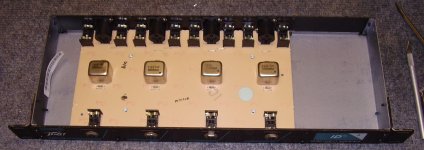
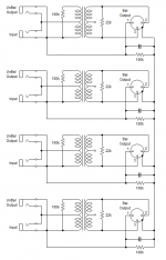
Hi all. I'm trying to understand the purpose of a simple resistor thats been designed into this circuit. This device is a quad, direct interface box, to allow a guitar to connect to a mixing board. (4 guitars, actually.) Its the 1.53M resistor in question. This unit has a completely isolated chassis and no common ground except for the barrels of the XLR connectors. Even those are plastic. There's a little metal tab that would contact the output XLR barrel, and those are all electrically connected together. Then, you have the 100k and 1.53M resistors in parallel, which connect that line to each DI's virtual ground. (XLR pin 1).
Having said all that, I'm trying to understand why the designers felt the need to add those four 1.53M resistors to the production cost. (Along with the additional circuit traces and through-holes.) They simply drop the 100k resistor to approx. 99.4k, and even then, those 100k resistors are 5%. Their normal production variance could be greater than the amount dropped by the 1.53M resistor.
I assume that engineers always have a good reason why they do a specific thing in a design. Anyone have any insight as to why they included those resistors?
I'm stymied. (BTW, this is a Peavey DI box. They haven't responded.)
Thanks all;
Artie
Edit: Btw, since I don't have any specs on this, I'm not sure whether it was intended for guitar input or line input, or, something else.
Attachments

Last edited:
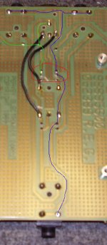
Here's one more pic:
Not the red circle is around the two resistors in question. Its easy to see that both ends are connected together to each trace. The blue line shows the path of the input/output virtual grounds, and the green line shows going to the XLR barrel connector tab and also through a jumper that feeds the other channels. (Thus, shorting them together.)
Not the red circle is around the two resistors in question. Its easy to see that both ends are connected together to each trace. The blue line shows the path of the input/output virtual grounds, and the green line shows going to the XLR barrel connector tab and also through a jumper that feeds the other channels. (Thus, shorting them together.)
Attachments
Perhaps, in certain circumstances it is necessary to increase the impedance to 1.53M and remove (clip out) the 100k resistor.
The parallel resistance is 93.9k not 99.4k. If you buy a thousand resistors now days you will find that they may have a 5% tolerance but the actual spread between the resistors are around 1%. They can just be up to 5% difference from the desired value.
I used to work for a company that had a certain resistance tolerance in their spec. I questioned why the numbers and came up with a previous batch of wire had an average resistance and the spec. was written in response to it.
Well the new wire had a different resistance and much of our production was now falling outside our spec. Once I recalculated for the new wire our target resistance shifted and we had fewer failures.
Maybe the batch of resistors they had were above 100k and they are trimming them down to get the target value.
Perhaps, but it would only be the impedance between ground and the XLR barrel, which doesn't make sense. (At least, to me.)
(This was directed at John's post.)
(This was directed at John's post.)
Maybe the batch of resistors they had were above 100k and they are trimming them down to get the target value.
That seems logical, but why would a resistor, in that position, be critical to begin with?
The front panel input overrides the rear panel input. So, for the sake of simplicity, I simply omitted one of them. (From each channel.)
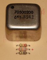
Btw, the resistor in question has a color code of: Brn, Grn, Org, Silver, Gray. That actually corresponds to 1.53 ohms, but it actually measures 99.4k with my meter. (The two in parallel, that is.) I haven't actually unsoldered one end and lifted it from the circuit. I suppose I should do that just to confirm the 1.53M value.
Btw, the resistor in question has a color code of: Brn, Grn, Org, Silver, Gray. That actually corresponds to 1.53 ohms, but it actually measures 99.4k with my meter. (The two in parallel, that is.) I haven't actually unsoldered one end and lifted it from the circuit. I suppose I should do that just to confirm the 1.53M value.
Last edited:
Are you 100% sure they're resistors? I've seen caps that looked just like resistors,but they were different colored. A value of "153" would be .015uf. It might make sense as a RF suppression cap.
Just a thought.
Just a thought.
Thats a good thought, and I did consider it. But the parallel measurement, with my DMM, implies that its 1.53M. Although, at this point, I agree that it might be a good idea to lift one end and take a new measurement.
It just means I have to tear the unit apart again. 🙄
I'll do that now. Back in awhile.
It just means I have to tear the unit apart again. 🙄
I'll do that now. Back in awhile.
Huh.
Maybe it's some kind of safety thing. In the event that the 100K's were to go open the 1.5meg resistors would still be there,to keep 'static' charges from building up? That still doesn't make a whole lot of sense though,any voltage high enough to nuke a 100K resistor is likely to cause other problems long before the resistors start to complain.
Value trimming could be a possibility,but as already mentioned,I don't see why it's that critical.
I dunno,I give!
Actually, I think you got it right in post #11. With one end lifted, it reads open and the 100k resistor reads the 99.4k. (Normal tolerance variation.) It appears as though it probably is a cap. That makes a lot more sense.
I'll edit the original schematic in a moment.
Its the component with the red arrow.
It doesn't appear that I can edit my first post, so here's the "corrected" schematic:
I'll edit the original schematic in a moment.
Its the component with the red arrow.
It doesn't appear that I can edit my first post, so here's the "corrected" schematic:
Attachments
Last edited:
If the three terminal output connectors are XLR connectors, then the schematic is very wrong!
On XLR connectors, pin #1 connects only to the chassis, not to any part of the audio signal.
On XLR connectors, pin #1 connects only to the chassis, not to any part of the audio signal.
Yeah, I see what you're saying. It is on the input side, but not the output side. In other words, only pins 2 & 3 are connected to the output of the isolation transformer, but pin 1 connects to the chassis ground of whatever the input device is.
Maybe this is why Peavey quit making them. 😀
Edit: Although, it appears that this is the same thing Jensen does with their transformers:
http://www.jensen-transformers.com/as/as007.pdf
Maybe this is why Peavey quit making them. 😀
Edit: Although, it appears that this is the same thing Jensen does with their transformers:
http://www.jensen-transformers.com/as/as007.pdf
Last edited:
The schematic connections in post #14 are very different from the connections in AS007.
Pin #1 should be connected to the connector shell and/or the chassis. All your pin #1's are connected to the wrong end of the capacitors.
Pin #1 should be connected to the connector shell and/or the chassis. All your pin #1's are connected to the wrong end of the capacitors.
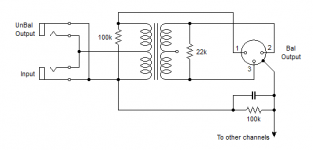
Hmmm . . . good catch. You made me go back and recheck my drawing. Sure enough, I got pin #1 connected to the wrong side of the 100k resistor. (The one on the transformer input. Not the one on ground.) Here's the final corrected schematic. (One channel shown.)
The connection of pin 1 still seems weird to me, but at least, this is exactly as its wired on the board.
The connection of pin 1 still seems weird to me, but at least, this is exactly as its wired on the board.
Attachments
- Status
- Not open for further replies.
- Home
- Source & Line
- Analog Line Level
- Resistor mystery.