Hello out there from Germany,
i blew up my JBL GTO 6000 car amp last week. A heavy box slit into the acrylic window, pushed it in (not broken) and all 10 MOSFETS from the PSU blew.
I still don't know why, the PCB did not touch the case bottom metal.
Mosfets were Fairchild FQP50n06, which are hardly to get here (20$ one!!!)
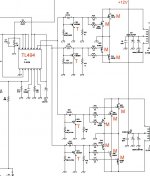
A TL494 PWM controller is steering 4 small transistors that switch the gates of 4 Mosfets for the normal channels of the amp and 6 mosfets that supply the sub amp. 2 transformers, a bigger one at the 6 and a smaller one at the 4 mosfets.
I replaced TL494, output transistors, mosfet gate resistors and added 4 bigger mosfets just for testing. it still works.
now my question to the electronic skilled:
can i replace these original MOSFETS:
http://www.fairchildsemi.com/ds/FQ/FQP50N06.pdf
with these i can easily get for 60 cent:
http://www.irf.com/product-info/datasheets/data/irfz48n.pdf
the data seems to fit except the "Avalanche Current" which is 50A on the original, and only 32A on the replacement device, although the replacement's Ids current is higher.
What do you think?
THANKS!!
i blew up my JBL GTO 6000 car amp last week. A heavy box slit into the acrylic window, pushed it in (not broken) and all 10 MOSFETS from the PSU blew.
I still don't know why, the PCB did not touch the case bottom metal.
Mosfets were Fairchild FQP50n06, which are hardly to get here (20$ one!!!)
A TL494 PWM controller is steering 4 small transistors that switch the gates of 4 Mosfets for the normal channels of the amp and 6 mosfets that supply the sub amp. 2 transformers, a bigger one at the 6 and a smaller one at the 4 mosfets.
I replaced TL494, output transistors, mosfet gate resistors and added 4 bigger mosfets just for testing. it still works.
now my question to the electronic skilled:
can i replace these original MOSFETS:
http://www.fairchildsemi.com/ds/FQ/FQP50N06.pdf
with these i can easily get for 60 cent:
http://www.irf.com/product-info/datasheets/data/irfz48n.pdf
the data seems to fit except the "Avalanche Current" which is 50A on the original, and only 32A on the replacement device, although the replacement's Ids current is higher.
What do you think?
THANKS!!
it should work , check also on and off times of the mosfets , u can use only 2 "new" mosfets and see if its working under small load .if its ok then u can put the others in .
the higher Ids means higher dissipation on the mosfets. you might not be able to push the amp as hard as you did with the original mosfets. basically, they would work though not as reliable as before.
Hi there,
the IRFZ is switching faster than the original FQP.
I read in another thread, that as higher the number of an IRF Transistor is, as more unsuitable it is for audio applications.
Why?
Should i go for the IRFZ46N with less current?
I knew about only one mosfet per polarity is needed per transformer. Saying i added 4 test mosfets, this was 2 for each PSU.
Can you imagine why they blew, and why _all_ of them blew as they are in 2 separate PSUs? Could a failure of the TL494 have caused this?
thanks!
I read in another thread, that as higher the number of an IRF Transistor is, as more unsuitable it is for audio applications.
it doesn't matter as the mosfets are used in the switching PSU as they are either completely on or completely off.
audio applications means that the mosfets are run in a linear region.
mh, no editing allowed.
a question that i forgot: Is the Gate resistor ok with 22 Ohms?
See the attached pic for gate circuit details
:edit: picture removed at member's request
a question that i forgot: Is the Gate resistor ok with 22 Ohms?
See the attached pic for gate circuit details
:edit: picture removed at member's request
i see u got no driver transistors , the pnp transistor is there to forse the mosfet to shot down only . if u got 10 mosfets then u need a buffer between the pwm chip and the power transistors
anyways
imho 22ohm is too much ,a bit less then 10ohm is more common
anyways
imho 22ohm is too much ,a bit less then 10ohm is more common
the fact i am new and under moderation totally scrambles the order of my posts.
the question to djQuan was referring to
sorry, i am really having a problem with no editing. I always get sth in mind i forgot to post.
So, in addition to the post with the picture:
I replaced the 1266 transistors with BC640 ( http://www.semiconductors.philips.com/acrobat_download/datasheets/BC636_638_640_5.pdf )
can that stay that way? are these ok for the job? 1266s are not available here.
thanks so much for your fast responses. 🙂 🙂
the question to djQuan was referring to
the higher Ids means higher dissipation on the mosfets. you might not be able to push the amp as hard as you did with the original mosfets
sorry, i am really having a problem with no editing. I always get sth in mind i forgot to post.
So, in addition to the post with the picture:
I replaced the 1266 transistors with BC640 ( http://www.semiconductors.philips.com/acrobat_download/datasheets/BC636_638_640_5.pdf )
can that stay that way? are these ok for the job? 1266s are not available here.
thanks so much for your fast responses. 🙂 🙂
I have built a few SMPS's and a car amp (200W, 500W) and that circuit is similar to the one I used.
I don't think 22R is too small. I used 100R and others use 47R. with the drivers I used in my schematic (www.djquan.angelcities.com/smps.html)the 220R resistors are 1k and gate resistors are 100R. the PNP transistors are 2N3906. I was able to drive three pairs of power mosfets for the 500W SMPS. the MOSFETS I used are 90A each(2 pairs for 200W amps, and 110A each(three pairs for 500W amp).
they are ok. just make sure the gate-source capacitance is not too large in comparison to the originals.
I don't think 22R is too small. I used 100R and others use 47R. with the drivers I used in my schematic (www.djquan.angelcities.com/smps.html)the 220R resistors are 1k and gate resistors are 100R. the PNP transistors are 2N3906. I was able to drive three pairs of power mosfets for the 500W SMPS. the MOSFETS I used are 90A each(2 pairs for 200W amps, and 110A each(three pairs for 500W amp).
djQuan - i could also get IRFZ 44 or 46, they have 49 / 53 Amperes. Should i take one of these?
they are ok. just make sure the gate-source capacitance is not too large in comparison to the originals.
What do you mean, "a buffer". How to buffer what where?
Why do i need that?
here's more from the psu:
M = mosfet, T= the blown transistors i replaced with BC639.
edit: picture removed at member's request
Why do i need that?
here's more from the psu:
M = mosfet, T= the blown transistors i replaced with BC639.
edit: picture removed at member's request
a buffer is the PNP transistor. it enables the output of the TL494 to drive the gates.
you don't need those since the circuit already has them.
are you sure te replacement has the same pinouts to the originals?
from what I know, 2SA transistors are ECB and BC series are CBE.
you don't need those since the circuit already has them.
are you sure te replacement has the same pinouts to the originals?
from what I know, 2SA transistors are ECB and BC series are CBE.
The BC 640 is a special one that has ECB. I had to do with it days ago and i remembered it had the Base on the side, so that was the first fitting trans. i had in mind.
I'll build the amp up with 10x 22R and IRFZ46N (53A) next week and give you feedback.
Thank you so much for that fast help and competence. 😉
I hope i can pay back someday.
Does anyone have a hint on how the whole thing could burn?
And how i could prevent that in future? The Amp's power cable as the amp itself were properly fused, no fuse tripped. I shut off by hand :/
The input capacitance of the original Mosfets is 1200pf typ, 1600pf max.
the input capacitance of the irzf46n replacement is 1700 typ.
max is not given.
is this too much?
the input capacitance of the irzf46n replacement is 1700 typ.
max is not given.
is this too much?
I think it would be fine. if unsure, you could buy a few and use for the first part of the powersupply and the high power without mosfets.
Go ahead
I have looked at the specs on both FETS and cannot see any problem in using them.
When looking at how the FETS are driven (in the schematic) the slightly higher capacitance will not be a problem.
Cheers
I have looked at the specs on both FETS and cannot see any problem in using them.
When looking at how the FETS are driven (in the schematic) the slightly higher capacitance will not be a problem.
Cheers
- Status
- Not open for further replies.
- Home
- Design & Build
- Parts
- Replacement mosfets for car amp