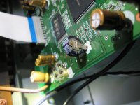
My Yamaha RX-V3000 AV receiver (around 2001) does not keep the settings in the memory and it is a pain to reenter them whenever the power goes off. I found that there is a memory backup capacitor "super capacitor" (C662) which is 0.047 F 5.5V (see photos). I located this component but it is on a circuit board that looks like it would be a major production to remove and I fear that I could cause damage trying to get that board out so that I could desolder it from underneath and then install a replacement. Could someone kindly answer the following:
1. Other than not being aesthetically pleasing, would it be OK if I removed the memory capacitor by snipping the solder tabs on the top side of the board that is more accessible, and then solder the leads of the replacement part to the remainder of the tabs that go through the board? (Or I could attach the replacement part with short jumper wires to these tabs if necessary?)
2. I am not familiar with this type of capacitor and to me it looks like 2 coin cell batteries back to back. It is my understanding that this capacitor slowly discharges and can retain the memory for a few days and then gets recharged when the power is back on (and thus it is not actually a battery at all.) Is there any possibility that when replacing this memory capacitor that damage could be done to the memory chips and are there any precautions that should be taken. I am assuming that I would receive the replacement capacitor in the discharged state, but should I discharge it by shorting its 2 leads to be on the safe side?
I want to be extra careful because I do not want to kill this receiver. For a short term solution I have the receiver plugged into an uninterruptible power supply that helps keep the settings during short losses of power, but the UPS battery seems to get depleted in a matter of hours and sometimes I like to unplug the unit for longer than that during times of thunderstorms. Also the UPS probably adds noise since it is not a clean sine wave. Thanks in advance for any advice.
Attachments
Read up on proper static-safe procedures first. You might damage the board when clipping off the capacitor,
so if possible desolder it. The new capacitor should arrive discharged, check with a voltmeter. Observe polarity.
https://www.minicircuits.com/app/AN40-005.pdf
so if possible desolder it. The new capacitor should arrive discharged, check with a voltmeter. Observe polarity.
https://www.minicircuits.com/app/AN40-005.pdf
Last edited:
A 5.5 V supercapacitor consists of two 2.75 V supercapacitors in series, hence the series-connected coin cell look. A single supercapacitor cell can't handle such high voltages. They are also known as electrochemical double layer capacitors, see Supercapacitor - Wikipedia They really are capacitors. For reasons of reliability, it's important they don't get hot, or at least not often.
I don't see any problem with your idea to snip the tabs, except that the tabs might drop out of the PCB if the point where they are attached to the PCB should get too hot when you solder the new capacitor to it. But that should be avoidable.
If you are worried about what could happen during soldering of a partly charged capacitor, instead of using a hard short, I'd rather discharge them through a small resistor. 0.047 F and 100 ohm gives you a time constant of 4.7 seconds, so after half a minute practically all remaining charge will be gone.