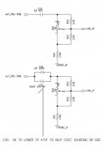
*see attached schematic
the LF pre trim for the woofer, the output of which then gets fed to the 1st stage amp, uses a 100uf (nonpolar electrolytic) and a 0.1 uf film cap in parallel
what is the function of the 100uf? to block dc into the amp/ to protect the amp?
what would happen if i removed 100uf and only used the single 0.1uf film cap?
on the HF tweeter pre trim im using a poly/foil cap that sounds very nice and much better than oem
so id like to get the same cap but in 0.1uf for the woofer
Attachments
Replace it with just the 0.1 - see if you still get a square wave on the output at 50Hz.
Kidding aside, the woofer wont benefit from the HQ cap in that position, certainly much less than the tweeter has per your observation.
Personally, I'd leave it as is, unless you can parallel up a bunch of films you happen to have already to reach 100uf. Sounds like an expensive waste to me, others may have different opinions.
the thought is since the mids are critical, and the xo freq is 1600 on this 2 way monitor, getting a better cap in place of the 100uf electrolytic, could be a very good thingReplace it with just the 0.1 - see if you still get a square wave on the output at 50Hz.
Kidding aside, the woofer wont benefit from the HQ cap in that position, certainly much less than the tweeter has per your observation.
Personally, I'd leave it as is, unless you can parallel up a bunch of films you happen to have already to reach 100uf. Sounds like an expensive waste to me, others may have different opinions.
Follow your thinking and give it a shot then. Is the circuit input really AC? You can measure that if you have a scope or DMM. If there's DC bias larger than the max signal amplitude, you can use a polarized part. They do make Al Els of better quality than what the OEM put there. Otherwise, even on ebay, I see they want $4 per 20 uF unit in quantity 5, so maybe for $50, you could have all film caps in 2 channels...
https://www.ebay.com/itm/284926054943?hash=item4256ea921
Or, you could fire up a simulator and see where that collection of resistors loading the 100 uF falls off as a High Pass filter, decide if that's realistic or something you want to keep, or if there's any "give" that would allow you to use a smaller cap there to save money.
back to my original question.. what does the 100uf do? what is its role in the circuit?Follow your thinking and give it a shot then. Is the circuit input really AC? You can measure that if you have a scope or DMM. If there's DC bias larger than the max signal amplitude, you can use a polarized part. They do make Al Els of better quality than what the OEM put there. Otherwise, even on ebay, I see they want $4 per 20 uF unit in quantity 5, so maybe for $50, you could have all film caps in 2 channels...
https://www.ebay.com/itm/284926054943?hash=item4256ea921
Or, you could fire up a simulator and see where that collection of resistors loading the 100 uF falls off as a High Pass filter, decide if that's realistic or something you want to keep, or if there's any "give" that would allow you to use a smaller cap there to save money.
To block DCthe LF pre trim for the woofer, the output of which then gets fed to the 1st stage amp, uses a 100uf (nonpolar electrolytic) and a 0.1 uf film cap in parallel
what is the function of the 100uf? to block dc into the amp/ to protect the amp?
You would DESTROY that woofer sound.what would happen if i removed 100uf and only used the single 0.1uf film cap?
Weak, tinny, buzzy,you-name-it.
Confirmation bias, you IMAGINE it sounds better.on the HF tweeter pre trim im using a poly/foil cap that sounds very nice and much better than oem
You actually can´t tell the original from the replacement in a DBT
Besides, define "sounds better" 🙄
Alone?so id like to get the same cap but in 0.1uf for the woofer
You might as well pull that woofer and mount a tweeter in its place; you will get about same result.
You seem to be from the school: "Brand/Price matters .... couldn´t care less about values" ....
Together with 100uF?
You actually won´t tell the original from the replacement in a DBT
Now look at the schematic: what does it show besides each and every part: BRAND or Electrical VALUE?
Now meditate about it.
As a side note, I find 100uF there way too large.
100uF and the about 5k impedance of that trim circuit give you a highpass frequency around 0.32Hz 😱
Completely outside any significant Audio frequency.
You could replace it by 10uF, now showing 3.2 Hz highpass, still well outside Audio,but a more manageable value.
Last edited:

So i can go with a 10uf non polar and no 0.1uf bypass ?To block DC
You would DESTROY that woofer sound.
Weak, tinny, buzzy,you-name-it.
Confirmation bias, you IMAGINE it sounds better.
You actually can´t tell the original from the replacement in a DBT
Besides, define "sounds better" 🙄
Alone?
You might as well pull that woofer and mount a tweeter in its place; you will get about same result.
You seem to be from the school: "Brand/Price matters .... couldn´t care less about values" ....
Together with 100uF?
You actually won´t tell the original from the replacement in a DBT
Now look at the schematic: what does it show besides each and every part: BRAND or Electrical VALUE?
Now meditate about it.
As a side note, I find 100uF there way too large.
100uF and the about 5k impedance of that trim circuit give you a highpass frequency around 0.32Hz 😱
Completely outside any significant Audio frequency.
You could replace it by 10uF, now showing 3.2 Hz highpass, still well outside Audio,but a more manageable value.
I am not a fan of exotic expensive capacitors. You pay a lot more but usually get little improvement, if any at all.
Im also a fan of value and i do trust my ears👍...so ill do away with the 0.1 and stay with the nichicon es..I am not a fan of exotic expensive capacitors. You pay a lot more but usually get little improvement, if any at all.
Just do it.what would happen if i removed 100uf and only used the single 0.1uf film cap?
given all the above info, im now thinking that removing the 0.1 and only using a 100uf ( or 47uf ) may be the best approach.
given a choice between a physically larger or smaller cap, is the larger the way to go?
given a choice between a physically larger or smaller cap, is the larger the way to go?
that´s NOT what "the above info" suggests.given all the above info, im now thinking that removing the 0.1 and only using a 100uf ( or 47uf ) may be the best approach.
given a choice between a physically larger or smaller cap, is the larger the way to go?
Just sayin´
Yeah 10uF would be fine with a corner of 3.2Hz. Depending on the design it might actually perform better with a 1uF and a corner of 32Hz. What is the monitor?
Please understand that the 0.1 in parallel with the 100uf was the manufacturers (or somebodys) attempt to make the woofer signal path "better".im now thinking that removing the 0.1 and only using a 100uf ( or 47uf ) may be the best approach.
The theory being that you can get a couple cheap components to sound like a more expensive one - or close enough. If you want to move in the direction of even better - theoretically - you should replace the Al El cap with film. The OEM felt it was too expensive to manufacture using such, so they found a cheaper solution. As a DIY / One Off situation, in comparison the decision to use a film cap is affordable.
Given that 47 / 10 / 2 / 1 uf values would each work (as suggested above), you could confidently buy just a pair of those 20 ufs off ebay for $15 - and done! What's to worry? Size? They might not fit on the board... I'm sure it's easy to find a film cap somewhere in this range of values that would.
The trim pot network resistance total is about 4K, not including the unknown power amp load, so a 0.1uF cap alone will block all the bass, ie everything below 227Hz. ( f=1/(2piRC) ) We need to know if the input has any DC and what is the output load impedance. If there is no DC from the preamp, then any capacitor is redundant, and you would be better with a jumper short instead. If there is DC then you need to know the polarity so that a polar cap can be oriented accordingly. 100uF (0.23Hz) is probably overkill, 1uF (23Hz) is minimal and 10uF (2.3Hz) a good choice. The 0.1uF is there because large caps can be inductive, but it is unlikely it actually makes any difference. Given that this is the bass channel, a high frequency bypass is completely useless.
- Home
- Amplifiers
- Solid State
- replace 100uf cap with 0.1uf ?