In the past I used an iMM-6 and configured REW with 'no timing reference' (set t=0 at IR start). Recently I got an EMM-6 mic and a Behringer UMC22 audio interface. Last weekend I made some measurements of a speaker I'm working on. I used the 2nd channel in and outputs for timing reference.
The FR plots look reasonable (given the low cost drivers), but the phase responses cycle a lot. I understand why, just not how to correct for this properly. Using the controls on the 'Impulse' tab I can click the button 'Set t=0 at IR start', or 'Estimate IR delay'. Both result in much nicer phase plots, but they do start to differ quite a bit as frequency rises.
Another option would be to click the 'Offset t=0' button, which lets me manually change the mic distance (and corresponding delay) to 1m, resulting in yet another fine looking phase measurement, but different again.
So my question is how to account for the right amount of delay.
There is no right amount of delay, just like there is no true phase.
You need some constant delay if you’re interested in summing the output of different sources. When designing a multi-way loudspeaker for instance.
The correct method is to measure all sources (drivers) in exact the same measurement setup. If you change delay afterwards, make sure you apply the same delay to every measurement. In some way it is cosmetic however.
Thanks for your answer Mark!
The goal indeed is to use the measurements for designing a crossover for a two-way loudspeaker. There's a couple of remarks I don't fully understand though..
By which you mean to say that phase is always relative to the distance between driver and mic? But if one is careful to keep the mic distance exactly the same between in all different driver measurements, doesn't that make the phase (per specific frequency) absolute?
I don't understand what you mean by this. Afaik, getting the delay (and thus phase) right can make a lot of difference in the summed response when working with higher crossover frequencies, right?
The goal indeed is to use the measurements for designing a crossover for a two-way loudspeaker. There's a couple of remarks I don't fully understand though..
There is no right amount of delay, just like there is no true phase.
By which you mean to say that phase is always relative to the distance between driver and mic? But if one is careful to keep the mic distance exactly the same between in all different driver measurements, doesn't that make the phase (per specific frequency) absolute?
In some way it is cosmetic however.
I don't understand what you mean by this. Afaik, getting the delay (and thus phase) right can make a lot of difference in the summed response when working with higher crossover frequencies, right?
You got it right. Phase at the mic is determined by the phase behaviour of the source plus the distance to the mic. Change the distance and the phase changes. That is why I mentioned ‘no absolute phase’, while electric it is there, at least at the frequencies we’re regarding.
With cosmetic I meant that any compensation for the pathway (mostly referred to as ‘removing excess phase’) isn’t needed for the acoustic summing of drivers at the mic position. It looks way better in the graphs though.
Most important is that you measure dual channel. And keep mic position fixed through measurements. You figured that out already, so keep up the good work.
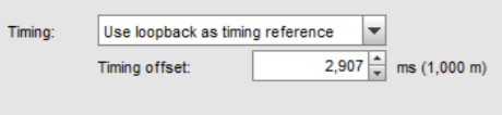
Have you got the timing offset the same as your measurement distance?

https://kimmosaunisto.net/Software/VituixCAD/VituixCAD_Measurement_REW.pdf
https://kimmosaunisto.net/Software/VituixCAD/VituixCAD_Measurement_REW.pdf
Attachments
You're welcome, you can also do it after the fact by moving all the measurements that far back in time so the fixed time of flight from the measuring distance is removed 🙂
That's exactly what I did. Using the 'Offset t=0' button in REW I adjusted the delay so that the 'cumulative shift' was 2.9152ms or 1000mm. I did this for both drivers. Then I exported both drivers' FRD files as well as an FRD file of both drivers in parallel. In XSim I connected both drivers directly to the amp, and imported the 'both drivers in parallel' FRD as an overlay. Only had to increase the distance (delay) of the midbass driver a little to get the modeled response within 1dB of the measured 'both drivers in parallel' response, which is to be expected given the driver layout. This tells me the phase measured for both drivers is on point.
Don't try to be overly millimeter specific. The time resolution of even 192kHz AD converters is limited. But I think that your approach is OK.
- Home
- Design & Build
- Software Tools
- Removing impulse delay in REW