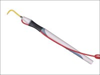
Rockford Fosgate single channel PM1000xbd1 amp.
My amp works fine if I switch it to use the internal pot for punch EQ. If I switch it to the external pot, then the amp is silent. The amp is only 6 months old, and the external EQ originally worked. I checked the switch inside the amp with an ohmmeter, and it seems to be fine. Can't find any cold solder joints. The RJ45 connector looks to be fine as well. Even tried a 2nd cable and 2nd Punch control. The LED on the punch control seems to work.
The punch control is wired as a simple 5K pot from 0 ohms to 5K.
Any suggestions or anyone know what the schematic looks like around this part of the amp?
GregGarner
Have you checked the op-amps in this circuit to make sure they are all receiving regulated voltage, and have no dc on their output pins?
Re:Check op amps
I have not checked op amps yet. The PCB that the switch is mounted on is vertical and may be hard for me to probe.
I was thinking maybe I could use a scope or a voltmeter to try to look at the 2 center pins on the switch to see what happens when I am in local versus remote mode, see if that gave me any clues as to why the remote mode isn't working.
Are there any older amps that use this same sort of bass boost circuit where it can be either remote or local, and does anyone think that maybe it would have a similar circuit diagram, where maybe I could look at an older schematic that is available to get an idea of how they do this circuit on the new amp?
Greg Garner
Re😛robe
That probe is a great idea, I will make one.
I have already looked at the wires in the connector, and the soldering of the connector, and I can see no problem.
I will connect the remote to the amp and see if I can trace continuity from the remote pins to inside the amp and to the switch.
GregGarner
That probe is a great idea, I will make one.
I have already looked at the wires in the connector, and the soldering of the connector, and I can see no problem.
I will connect the remote to the amp and see if I can trace continuity from the remote pins to inside the amp and to the switch.
GregGarner
- Status
- Not open for further replies.
