Pi Manufacturing came highly recommended as a source for reasonably priced, high-quality RG58 cable assemblies. It seems they've shuttered their operation as of a few weeks ago.
https://www.leapmicro.com/password#:~:text=The company will cease operations,Thank you.
Typical big-name internet resellers seem to have a multitude of products of potentially dubious origins and performance. Since I am not sure how to check the cables properly, I'd like to ensure that I get assemblies with a proper RG58 cable and properly spec'ed / assembled terminations.
Any advice is appreciated.

^ Thank you. Much appreciated. I tried them, and I also took a chance on Showmecables.com. Admittedly, I also took a flyer on some cables from Amazon branded / sold as TUOLNK. I don't have a decent LCR meter to check the cable impedance, but as long as there are no obvious flaws, they'll be fine in the short-run / relatively limited bandwidth applications for which I'll use them... I hope.

What frequency range are you working in? RG58 is 50 Ohm at high frequencies. You need a network analyzer or TDR to validate the cable assembly. What are you using it for?
Standard audio 20Hz to 20kHz. That's unlikely to change, but it might. I'm using them as patch cables between oscilloscope(s) and other test gear / DUTs.What frequency range are you working in? RG58 is 50 Ohm at high frequencies. You need a network analyzer or TDR to validate the cable assembly. What are you using it for?
Edited to add - thank you also for the note around proper testing. I (obviously) haven't much of a clue around this topic. I mainly just wanted to get some quality cables that wouldn't adversely affect basic distortion and other standard audio equipment measurements. Would that testing also apply to 50 Ohm 'shorting plugs'? I've read that suspect products can be way off spec, but to essentially not worry about it unless they measure as a dead short. Amphenol products from reputable sources are (to me) expensive, and apparently as no shock to anyone some Amazon / Ebay sellers sell not-so-great ones.
Last edited:
You really don't need RF cable for audio frequencies, but a quality RF cable will be perfectly adequate. RF cables have to use polythene or PTFE insulation for low loss up at GHz frequencies, audio doesn't require this, most insulation materials are usable, including more flexible ones.
What connector are you using? BNC? Just signal level?
What connector are you using? BNC? Just signal level?
Hi Mark -
Thank you for your continued help. For transparency, this started as I prepare for the arrival of a Quantasylum unit. I was reading their page on recommended tidbits one might need.
The connectors to the oscilloscope, (two of the) oscillators, the Quantasylum and other 'professional' type gear are BNC. The connections to a Focusrite unit (that may or may not stick around) are 1/4" TRS or XLR. The connections to DUT will either be RCA, XLR or something cobbled together by yours truly from a load bank to the input of the 'tester'.
Edited to add - I should answer your other question. Both signal level and speaker level.
A 10:1 probe is normally used for a 'scope, that gives you full bandwidth of the scope without loading the signal being observed much.
No-one ever really uses a 10:1 probe on the 1:1 setting (for good reasons)
If you use 50 ohm cable into a 'scope and it has 50 ohm termination option, you can select that to get full bandwidth, but that's very heavy loading for most circuits (standard for RF signal level, not for audio signal level!)
If you use 50 ohm cable into a high impedance 'scope input, audio will see this as a capacitive load, and the 'scope bandwidth will be reduced markedly (but audio should be OK, we're talking MHz really)
If you are probing within a circuit always use 10:1 probe on 10:1 setting, not 50 ohm cable to the 'scope, there's too much capacitance that way to avoid upsetting what you are probing. For an amp or preamplifier output, it can handle the capacitance, only a power amp can handle a 50 ohm termination though (and you might need to worry about power dissipation then).
BNC connections favour RF coax, connectors are available for several common diameters of coax. If you learn to solder your own connectors you can bulk buy cable and connectors and reduce the cost. It is fiddly though.
^ I did more reading... I fully admit that I get completely turned around when it relates to some of 'this'... Rereading, and rereading to make sure I understand what I've read is a good thing. Impedance matching and signal bounce are well beyond my realm. 🙂 Loading... I should be able to grasp, but maybe not. I don't want to veer too off track even in my own thread that's not titled "teach Patrick the basics", but...
Well-noted and understood re: using scope probes for 'probing' measurements. I purchased a few well-regarded sets, and I calibrated the scopes with the scope probes for attenuation and set the probes themselves checking for the over / undershoot and adjusted each set. With one exception (noted by the process being followed) they're always set to 10:1 attenuation. There is one process (EEVblog's measurement of PSU ripple) where he recommends a 1:1 setting, but that's neither here nor there. The rated bandwidth is beyond the 5:1 or 10:1 ratio commonly discussed, and the probes are 100Mhz. The probes show the rise times, resistance/impedance, and capacitance etc., but I admit that makes my eyes glaze over, so I calibrated the scopes against the probes for attenuation and set the probes' capacitance for the over-undershoot with the little potentiometers on the probes. I followed the process in the scope manual and called it a day.
With regard to the loading, I appreciate the insight, and perhaps I should have been more clear and/or I'm just wrong. I was / am using BNC to BNC as a patch to the oscilloscope from one or two pieces of gear more for 'monitoring and visualization' not really testing. For some reason, I like to have the scope display and verify the frequency and amplitude from the signal generator, particularly a generator with no display.
Back to more of a point - I admit that I'm still a bit lost...specifically as it relates to cabling between devices. I'm going back to your comment about loading the signal (source, I assume is related, but again... oof). If I read loading the signal, I immediately think voltage attenuation. If I think of loading the source, I think of the current flow. If a signal generator (that's acting like a voltage source) sees a low impedance load at a certain output voltage setting... higher current => more power required from the source. If the signal from the source is attenuated, the 'receiver sees a lower voltage than transmitted', but you tell the scope through the menu, that you've attenuated it at a particular ratio (say 10:1), and it just does the math. Am I even remotely on track? My scope does have a 50 ohm termination option, but that seems (as you've said) to be for much higher frequency testing, and the high pass filter is at 200MHz (also Vpk is limited to 5V). I don't see myself varying from 1Mohm, but I could again be wrong.
Practically...
1) A ShibaSoku A70 (a distortion analyzer with a built in oscillator) has a switch for the output impedance for the oscillator of 600 ohms. I've read the manual, but it confuses me mightily. It says
"Push the “A&B 600 Ω LOAD” switch for turning ON (LED lights) to terminate the output with a 600 Ω resistor. When it turns OFF (LED goes out), output resistance selected is 600 Ω"
The LED lit along with the standard 1Mohm setting on the oscilloscope and a direct BNC to BNC connection between the two seems to work absolutely wonderfully. The displayed output of the oscillator matches to within <0.1% of the scope display for amplitude and frequency. When playing with buttons (dangerous, I know) and toggling that option to LED off, the voltage displayed on the scope doubles almost exactly. I have no earthy idea why, and even after reading and searching for what the difference between terminating the output with a 600 ohm resistor and setting the output resistance to 600 ohms might be... I continue to be lost. So, I moved on. 🙂
2) An oscillator like the Akitika. I just took RCA out from the Akitika to an RCA to BNC to the oscilloscope. I verified the output voltage of the Akitika with a DMM against the scope.
Any concerns? Is it appropriate to connect the scope to a signal generator this way?
Once again... even after reading... and reading... there are gaps in my fundamental knowledge.
If these are test bench cables you should consider the double shielded version of whatever coax you choose. Keeping noise out of your measurement is a major issue, especially across the wide dynamic range of modern test equipment.
I started with generic RG174 with a cheap spiral wrap and after several iterations I now use double braid RG316 for my test bench coax pigtails.
I started with generic RG174 with a cheap spiral wrap and after several iterations I now use double braid RG316 for my test bench coax pigtails.
If you set the output or source impedance to 600 ohm and have a 600 ohm load the output should be one half of what it would be ( a voltage divider) if the input impedance is 1M.
This would be the same if the source was 50 ohm and the load is 1M.
At RF frequencies, one wants source impedance to be the same as the transmission line(cable) impedance and the termination impedance so that there are no reflections on the line. In other words the forward or incident wave gets fully absorbed in the load with minimal reflection back to the source.
^ Thank you! I clearly have more reading to do. When I read the sentence in the manual... that's definitely not the way I envisioned what they were describing.
In the specifications section of the manual, it says...
3.1.1. Output Impedance · Balance/unbalance: 600 Ω terminator ON/OFF. Independently set for A and B channels.
In the operating instructions it says...
Push the “A&B 600 Ω LOAD” switch for turning ON (LED lights) to terminate the output with a 600 Ω resistor. When it turns OFF (LED goes out), output resistance selected is 600 Ω"
I clearly have something backwards in my brain.
With the scope set to 1Mohm input impedance.
Voltage of oscillator set to 2.000Vrms (display).
LED switched off => "600 ohm load out"
DMM reads ~4Vrms. DMM isn't terribly precise / accurate with low AC voltages.
Scope reads 4.055Vrms
Voltage of oscillator set to 2.000Vrms (display).
LED switched on "600 ohm load in"
DMM reads ~2Vrms
Scope reads 2.023Vrms
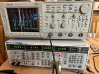
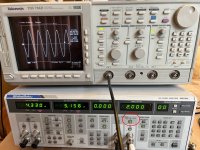
Pics if they're helpful at all. The LED being described is circled in red.
Something ridiculous is just not getting through to me...
Mainly... I thought having the LED lit "600 ohm in" was proper because the measurements agreed, but now I'm not so sure.
If anyone is wondering why I'm trying to to understand this.. and why I was bothering to try and measure it...
I was planning on using this oscillator (or one of a few others) as the input signal for amp/pre-amp measurements. I was / am trying to understand the voltage output to make simple gain calculations etc. If the input impedance of the pre-amp or amp or the cabling impedance (I don't think so) along with the output impedance of the signal generator affects the actual voltage to the DUT, then... that's important. If I simply trusted the displayed output on the oscillator without questioning or knowledge of what I was screwing up while pressing buttons, my calculations / measurements for gain etc. would be completely off. For oscillators with no displays, my plan was to verify their output with the scope before using them for measurements. If the relative in/out impedances of those devices and the scope and/or the pre-amps / amps is important, then I have work to do. I haven't even bothered to look at those specs yet to see what I may have misinterpreted.
I need to get back to basics. I've missed something.
I truly appreciate everyone's patience. This started off as a simple... what cables are good? It's evolved into basics of measurement techniques for dummies. I'm sure all of this has been covered elsewhere and people are repeating what's been written 100's of times. I've probably even read it, but clearly I just don't grasp it.
So... thank you!
In the specifications section of the manual, it says...
3.1.1. Output Impedance · Balance/unbalance: 600 Ω terminator ON/OFF. Independently set for A and B channels.
In the operating instructions it says...
Push the “A&B 600 Ω LOAD” switch for turning ON (LED lights) to terminate the output with a 600 Ω resistor. When it turns OFF (LED goes out), output resistance selected is 600 Ω"
I clearly have something backwards in my brain.
With the scope set to 1Mohm input impedance.
Voltage of oscillator set to 2.000Vrms (display).
LED switched off => "600 ohm load out"
DMM reads ~4Vrms. DMM isn't terribly precise / accurate with low AC voltages.
Scope reads 4.055Vrms
Voltage of oscillator set to 2.000Vrms (display).
LED switched on "600 ohm load in"
DMM reads ~2Vrms
Scope reads 2.023Vrms
Pics if they're helpful at all. The LED being described is circled in red.
Something ridiculous is just not getting through to me...
Mainly... I thought having the LED lit "600 ohm in" was proper because the measurements agreed, but now I'm not so sure.
If anyone is wondering why I'm trying to to understand this.. and why I was bothering to try and measure it...
I was planning on using this oscillator (or one of a few others) as the input signal for amp/pre-amp measurements. I was / am trying to understand the voltage output to make simple gain calculations etc. If the input impedance of the pre-amp or amp or the cabling impedance (I don't think so) along with the output impedance of the signal generator affects the actual voltage to the DUT, then... that's important. If I simply trusted the displayed output on the oscillator without questioning or knowledge of what I was screwing up while pressing buttons, my calculations / measurements for gain etc. would be completely off. For oscillators with no displays, my plan was to verify their output with the scope before using them for measurements. If the relative in/out impedances of those devices and the scope and/or the pre-amps / amps is important, then I have work to do. I haven't even bothered to look at those specs yet to see what I may have misinterpreted.
I need to get back to basics. I've missed something.
I truly appreciate everyone's patience. This started off as a simple... what cables are good? It's evolved into basics of measurement techniques for dummies. I'm sure all of this has been covered elsewhere and people are repeating what's been written 100's of times. I've probably even read it, but clearly I just don't grasp it.
So... thank you!
Attachments
I would not be so concerned, what matters is what you measure and how you measure it.
A generator that has 600 ohm source Z is meant for 600 ohm load Z, for a calibrated output.
FYI, I am not sure what DMM you are using to measure AC but look at its specs for AC. Many DMM are calibrated for use with line voltages only. I use a old HP 3478A, it has excellent AC specs, refer to its data sheet for a comparison. Glad to help you out even if our discussion goes beyond cables.
^ Thank you!
For anything requiring accuracy / precision, my plan was to use the scope for AC voltage measurements.
For rough ballparks of "is this kinda sorta working" I typically use a cheapy handheld meter for any frequencies between 40 and 500Hz. All the meters I have should be okay down to ~1V. The EEVblog one I bought to support his channel notes specific ACmV specs also (copied below). I use it when I think I may need a little more precision / accuracy, but it's still not a scope.
I really truly do try to RTFM and understand what I'm reading... but... 🤷♂️ I still get lost in the weeds.
Mainly... I'm trying to learn the basics of amp/pre-amp measurements and attempting to do them 'as properly as I can'.
As I suspected the DMM is designed for measuring AC line, 50/60Hz, the 440Hz spec is for use in aircraft, as that seems to be the std freq that they use.
As an experiment you can measure the AC frequency response of your meter by comparing it to what you measure with the scope in parallel
That’s why are here to help everyone learn, including myself
BTW, good luck with your Quantasylum, lots more to learn 🙂 what model did you purchase?
As an experiment you can measure the AC frequency response of your meter by comparing it to what you measure with the scope in parallel
That’s why are here to help everyone learn, including myself
BTW, good luck with your Quantasylum, lots more to learn 🙂 what model did you purchase?
Last edited:
Oooooooooh.... wait... did I misinterpret?
That's why I like pictures. I assumed... that the squiggle under range meant that it was good for between 10 and 500 Hz as an example with a certain level of precision / accuracy. Then... between 500 and 800 Hz it was still usable, but the accuracy / precision dropped a bit.
I always like cross-checking measurements / results between pieces of gear. I suppose it comes from my old life validating testing procedures / equipment. That's how all the questions about the mystery button 'came to light.' <groan> 🙂
When I don't even know what I'm looking at... it makes me feel a bit foolish reconciling what I used to be pretty darn good at with being a total neophyte in a different area.
^ Bear with the dodo, please.
So... I should have read the top set of specs (loosely) interpreted as...
This ACVM is intended to be used at a few common base frequencies vs. a range. Those frequencies are ~50 to 60 Hz ... OR 45 Hz OR 440Hz. Those are typical frequencies around which this thing was designed and intended for use. The precision / accuracy quoted is for frequencies near to those and those only.
It's NOT to be interpreted as...
This precision / accuracy stated is good for frequencies between around 50 to 60 Hz and between around 45 to 440Hz.
Good grief!
Not those specific frequencies but in the range of those frequencies, the typical is for the accuracy of measurement.
- Home
- Design & Build
- Equipment & Tools
- Reliable Source For RG58 BNC - PiMFG Is Closed