Anyone know where to get a recone kit for a Delta Pro 15? They don’t seem to sell them direct (OEM only). I had one just die open circuit the other day testing a tube amp - no sign of overload. It’s probably 15 years old, and only $150 to outright replace so it won’t break the bank, but I’d hate to just throw it out if there’s a cost effective way to fix it. No, I’m not taking it to a shop and paying $149 to rebuild a $150 speaker, but I’d buy a recone kit if it was reasonable.
I’ve also got a pair of LAB12’s with ripped foam surrounds, weakened from too much UV in my old truck. Otherwise working. If I could find new surrounds that are large enough I could fix those too.
I’ve also got a pair of LAB12’s with ripped foam surrounds, weakened from too much UV in my old truck. Otherwise working. If I could find new surrounds that are large enough I could fix those too.
When I encounter a "wholesale only" vendor, I usually ask them who sells their products at retail for a referral.
From their web page, Eminence shows these companies as potential suppliers. They sell their recone kits through these companies and others.
Recone Info | Eminence Speaker
And just google "eminence recone parts" and get a bunch of hits, first on is this:
Eminence speaker Recone Kits Archives | Speaker Exchange
Just as an example.
Or another specifically:
Recone Kit - Eminence(R), for Delta Pro 15ARK 15" | Antique Electronic Supply
Last edited:
If not a dedicated recone kit, you can certainly get spare parts and assemble it yourself.
The most critical one is the voice coil because you have NO tolerance there, gap width is so small and cluttered that you need exact same diameter VC ... but that shouldn´t be any exotic value, Eminence in general is quite generic he he.
You have slightly more elasticity when choosing spider and cone, a few mm difference won´t hurt anything.
Shopping around you should be able to find usable VC, spider and cone; dust cap and gasket are not critical at all.
Maybe Eminence datasheet states exact VC diameter (didn´t check), but if not, maybe some commercial offerings are stated as "Delta Pro suitable replacements" or something.
I also HATE to junk perfectly repairable speakers.
EDIT: look what the cat brought:
Genuine Eminence Recone Kit for 15" Delta Pro 15A, 8 Ohms, EM-RK-DELTAPRO15A
You might add the foam edges to the order to save on shipping (I guess).
Last edited:
If you don't buy a completely assembled recone kit, i.e. VC, spider, cone and surround already glued toether, you'll need also more information on the VC, either from the manufacturer or from a reputable speaker repair shop. Is it over/underhung? What's it's offset etc.?
Simply Speakers have some very informative videos at YT showing the reconing process.
Best regards!
Simply Speakers have some very informative videos at YT showing the reconing process.
Best regards!
So it looks like I *can* get them without spending well north of $100 for the kit. $55 is reasonable - but that does translate to over $150 for getting it done (double the price on the kit, and add an equivalent amount for labor). Getting the coil height right shouldn’t be *that* hard - the spec sheet does have the gap depth and x-max values. With conventional motors like these it should be a matter of centering it so it overhangs by 4.3mm. Their x-max values are the actual overhang amount, not some “fudged” value like xvar. When I can measure the actual winding length I can be more sure.
Hey! I thought *you* would recone it! 😕but that does translate to over $150 for getting it done (double the price on the kit, and add an equivalent amount for labor).
Where´s the DIY spirit? 😉
And yes, the above method to calculate overhang is reasonable.
Yes, seems reasonable. The most critig parameter indeed is the VC gap. Anything other mechanic relevant can be measured and calculated. BUT: In case of an underhung VC correct positioning in the gap remains tedious.
Best regards!
Best regards!
Oh,there is a very simple trick to solve that.
Suppose, just as an example, that top plate is 10mm thick, but voice coil winding is 6 mm.
You get a trusty ruler and a very fine point marker, and mark a line on VC former 2 mm above winding end, then when assembling use that line to vertically center voice coil, aligning it with top plate edge.
Suppose, just as an example, that top plate is 10mm thick, but voice coil winding is 6 mm.
You get a trusty ruler and a very fine point marker, and mark a line on VC former 2 mm above winding end, then when assembling use that line to vertically center voice coil, aligning it with top plate edge.
Hey! I thought *you* would recone it! 😕
Where´s the DIY spirit? 😉
And yes, the above method to calculate overhang is reasonable.
That’s why I wanted to find out about getting the kit myself. I first went to the Eminence site, only to find they only sell thru reconers. My experience with repair shops is the price is double the kit price plus an equivalent amount in labor, adding up to the Parts Express price for a new one. Back in the day when I used to blow speakers all the time, places like Speaker Exchange wouldn’t sell you *kits* - spare parts used to be closely guarded. Just cheaper to get a new one from McGee (then MCM, Consolidated, and PE over the years). The reasons cited was that the manufacturers didn’t want their reputations soiled by hack jobs. I haven’t blown an LF driver in years, other than on purpose, and it certainly surprised me that one in a 2x15 cab just quit for no reason. I’m certainly willing to give it a go before just ordering a new driver - that system is not in the critical path. I dropped in a pair of Kappa15LFs that I had on hand for the time being. The grills don’t fit well with those, and I had another project in mind for them so it’s not a long term solution. It does let me test my new 6x6550 monoblocks with full music power. It’s loud, very loud, but very clean.
My last dead eminence happened where the tinsel attaches to the vc wire. It was a very easy fix.
Jn
Jn
Yes, seems reasonable. The most critig parameter indeed is the VC gap. Anything other mechanic relevant can be measured and calculated. BUT: In case of an underhung VC correct positioning in the gap remains tedious.
Best regards!
The pole plate thickness (VC gap height for normal conventional motors) is specified in the Eminence data sheets. And their x-max values are calculated in the conventional way (Lvc-Hg)/2. I guess that is ether for reconer information, or to get an idea of how much more excursion you can push before BL takes a dump (some fraction of gap height). Some data sheets from other manufactures also specify winding length - and from that you can tell what the real x-max is.
Conventional ferrite motors don’t usually have underhung coils. The cost of replacing everything in my arsenal with neo is enough to say the hell with it all.
That.My last dead eminence happened where the tinsel attaches to the vc wire. It was a very easy fix.
Jn
Was chiming in to say exactly same.
Given the "for no apparent reason" bit it might very well be a open tinsel wire (relatively easy to replace) *or* broken VC wire *just* reaching the tinsel wire joint which takes steady hands and very sharp eye to mend.
Check under good light, using closeup reading glasses (+4 diopters) or even jeweller´s loupes (10-15X)
An old trick to check tinsel wires is to apply some DC to speaker 😱 , say 5V from a PC supply, in principle it will not react (it´s open) and move it back and forth with your fingers, also move tinsel wires around.
At some point they might make contact again, confirming the suspicion.
Working in a darkened room will show the blue sparks where the break is.
IF Eminence used an eyelet as the joint, it´s easier to repair; if , like many do, they just punched through cone paper, passed tinsel wire through hole, wrapped voice coil wire around its end, soldered it "in the air" and glued/gooped the whole junction for stiffness, it´s way more annoying.
In any case, check it, you might even need no new kit at all , just lots of patience and dexterity 😱
Originally Posted by Kay Pirinha
Yes, seems reasonable. The most critic parameter indeed is the VC gap. ......
Best regards!
Both true but the ultracritical gap parameter is not lenght but **diameter**The pole plate thickness (VC gap height for normal conventional motors) is specified in the Eminence data sheets. And their x-max values are calculated in the conventional way (Lvc-Hg)/2. I guess that is ether for reconer information, or to get an idea of how much more excursion you can push before BL takes a dump (some fraction of gap height).
Gap width is half the difference between pole piece diameter (so internal diameter) abnd hole punched/turned in top plate (external diameter).
Typical value for a *good* speaker is 1.5 mm (audio car monstrosities can have up to 4 mm gaps, cheap chinese speakers up to 2 mm or worse)
Now voice coil wire and former take about 80% of that, you *NEED* at least 0.1mm free space between former and pole piece , preferrably 0.125mm , same free space "outside", so voice coil can move *a lot* back and forth (peak to peak X Max) without scratching, and you realize diameter tolerance is microscopic.
Last edited:
The tinsel leads are well-gooped where they attach to the VC wires. First thing I did was pull the dust cap for a look-see. I would need something that dissolves goop without dissolving the cone in order to even check it. Moving things around doesn’t seem to help any - I already tried manually moving things to X-lim and pulling on the tinsel leads.
My most common failure in compression drivers is the lead-in wires fracturing, where the coil meets the diaphragm. The wire is subject to constant flexing, at fairly high frequency. Often I can take a turn off it and fix it, but it becomes even more prone to the same failure mode. It will often last until I can order a new diaphragm, though.
My most common failure in compression drivers is the lead-in wires fracturing, where the coil meets the diaphragm. The wire is subject to constant flexing, at fairly high frequency. Often I can take a turn off it and fix it, but it becomes even more prone to the same failure mode. It will often last until I can order a new diaphragm, though.
You should be able to scrape the goof off. In fact, just scrape a little off the vc wire insulation to check continuity.
My experience with compression drivers is that they fail exactly where you said. However, the reason I find is that the vc wire is not supported by epoxy, so is able to move, and it is still within the gap field. The current flexes the loose wire until if fails due to fatigue. Under a microscope, this can be seen as slip plane dislocations on the surface of the wire near the break.
This is also the primary failure mode when an amplifier is clipping. The clipping harmonics which are ultrasonic and at or near the resonant frequency of the loose wire in the gap can very quickly kill the wire.
Selenium had this issue with their D205TI tweeter, I contacted the factory and sent them detailed pics and drawings explaining the problem and how to fix it as even the replacement diaphragms had the fault. I simply epoxied the loose wire in place on the replacements. All you have to do is support the wire until it is completely outside of the gap flux. Five gap widths should be sufficient for field dropoff.
They seemed to have discontinued the product, I would guess because of returns, but have no idea.
Jn
Last edited:
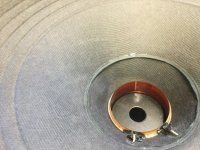
The goop doesn’t exactly scrape off. I’m having a hard time getting it off at all - it’s sort of rubberized. Came off the cone in one piece with the wire still embedded. But taking a look closely I’m seeing something concerning, which might have been the reason for failure. It doesn’t appear to be built correctly in the first place. These drivers are supposed to be overhung coil. I’ve had dust caps off the 12” version before, and the coil overhangs the gap like one would expect. This one is offset the wrong way. I have to push the cone *up* significantly to see any coil. It also plays louder that way. First image is in rest position, second is with me pushing up in the cone. I may want to recone it anyway, just to put the coil where it’s supposed to be.
Attachments

Last edited:
- Home
- Design & Build
- Parts
- Reconing Eminence ?