Hi Guys,
wondering if you can help with a recommendation of a solution for me?
I have a DAC with an output with a max of somewhere between 1v and 1.25v
My preamp is passive, essentially just a volume attenuator.
My power amps have a low gain, but an input sensitivity of max 1.5v
The output from my speakers is too quiet with this passive pre, so I'd like to add a little gain, either in the final stage of the dac or to join the passive preamp and turn it to essentially be active. This way I can get the most out of my current amps and speakers.
I've tested with a Yamaha C-4 active preamp instead of my passive and I can easily get the gain and ultimately the volume levels I'm after, but I didn't like the sound anywhere near as much with this extra device in the middle.
So what I'd like is to try a very simple opamp gain stage in the chain, before the preamp/attenuator. I would like this to be as simple and musically transparent as possible. Real short signal path and ideally with a small component count where I can use nice high quality components whilst keeping it relatively cheap. Ideally with no coupling caps in the mix. I guess I'm only looking for pretty low gain solution.
I have a nice low noise +-12v to +-15v power supply already I'm using with my buffer stage.
Does anyone have any recommendations for circuits/solutions I could try?
Ideally either very simple, so I can breadboard it easily or something where boards are already available.
Maybe there's a simple headphone amp solution already which I could adopt?
thanks,
James
You probably won't hear the difference between 1V and 1.5V. If your amp is too quiet at max volume then you need more power or more efficient speakers (or a smaller room). Or something needs repairing, or is telling lies in its spec.
Hi,
Tweek the gain of the DAC or the power amplifiers,
the latter is relatively very easy. Buffer stage ?
Changing that to gain is also an option.
rgds, sreten.
Tweek the gain of the DAC or the power amplifiers,
the latter is relatively very easy. Buffer stage ?
Changing that to gain is also an option.
rgds, sreten.
You could add the gain stage to the output of your attenuator, which would solve any cable capacitance rolloff caused by the passive attenuator's output impedance.
My preamp is passive, essentially just a volume attenuator. My power amps have a low gain, but an input sensitivity of max 1.5v
The output from my speakers is too quiet with this passive pre, so I'd like to add a little gain, either in the final stage of the dac or to join the passive preamp and turn it to essentially be active. This way I can get the most out of my current amps and speakers.
Are you saying there isn't enough volume even at no attenuation? If not, then there's no problem (other than the position of the volume control).
Is there any loss in the attenuator at full on?
Last edited:
.
Unfortunately, it's not actually that simple. A volume control is not trivial, it's supposed to work with the associated preceding and following circuits. We all wish it would be simpler, but it isn't.
However, it seems you already have what you need, which is a line level (nominal 1 volt) output feeding a line level input. It's just that you want to be able to vary the input to the amp.
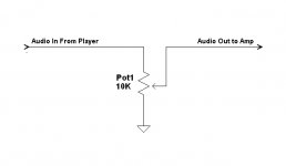
Have you considered something as simple as the circuit below? The shown value of the pot is arbitrary, it could just as well be 2k. In fact lower is better, but not less than 2k. It's a volume control so it should be a log pot, also called an audio taper pot, but if you just want to test the idea any pot will be fine.
This circuit theoretically violates the rule that output impedance be 1/10th of the following input impedance, but it might very well work anyway.
On a strictly personal note, I wish nobody had ever come up with the term "passive preamp." It's an oxymoron and there's no such thing.
.
Unfortunately, it's not actually that simple. A volume control is not trivial, it's supposed to work with the associated preceding and following circuits. We all wish it would be simpler, but it isn't.
However, it seems you already have what you need, which is a line level (nominal 1 volt) output feeding a line level input. It's just that you want to be able to vary the input to the amp.
Have you considered something as simple as the circuit below? The shown value of the pot is arbitrary, it could just as well be 2k. In fact lower is better, but not less than 2k. It's a volume control so it should be a log pot, also called an audio taper pot, but if you just want to test the idea any pot will be fine.
This circuit theoretically violates the rule that output impedance be 1/10th of the following input impedance, but it might very well work anyway.
On a strictly personal note, I wish nobody had ever come up with the term "passive preamp." It's an oxymoron and there's no such thing.
.
Attachments
That's the point. 🙂You could add the gain stage to the output of your attenuator, which would solve any cable capacitance rolloff caused by the passive attenuator's output impedance.
Also important that any gain (beyond a trivial, say, 2X) will make you lose headroom, and if heavy handed (beyond a mere 5X) you may even get into clipping ... which you will not solve by lowering volume because that control will be after said clipping.
You could add the gain stage to the output of your attenuator, which would solve any cable capacitance rolloff caused by the passive attenuator's output impedance.
Yes, we could call that combination a "preamp"!
.
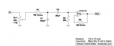
This post kinda nagged at me so I decided to post something that's actually what you asked for. The below circuit might serve your needs.
Circuit notes:
Rv1 is, of course, the volume control. It also acts together with R2 to set the input impedance, which is the parallel value of Rv1 and R2 (Rv1 || R2), in this case about 25k.
R1 and C1 together shunt high frequencies (around 100kHz) to ground. This is desirable because op amps can be in oscillation even if you can't hear it, and this filter guards against that. The 100 ohm resistance of R1 is otherwise insignificant. R1 and C1 can be omitted if you insist, but there's really little point in doing that.
C2 blocks DC.
C2 and R2 act together to form a high-pass (bass rolloff) filter that comes in a bit below 20Hz.
R2 is also the bias resistor for U1a. Omitting C2 and R2 is not recommended because then U1a must draw its bias current through variable resistance Rv1, which is not desirable.
Inserting a quick note, in my view capacitors are too much worried about. It's observable that internationally known gurus put in capacitors whenever and wherever they're judged necessary, which really should tell us something.
U1a is a buffer, and the point of this circuit in the first place. It's the nature of op amps that connected in this way they have unity gain, extremely high input impedance, and extremely low output impedance. This provides absolute separation between preceding and following circuits, which in audio is pretty much always what you want.
U1a is specified as an OPA2134, and in this case the much cheaper and equally satisfactory (in my opinion) NE5532 cannot be substituted. This is because of the bias current flowing through R2, which adds a DC offset to the output. The bias current of the OPA2134 is a worst-case 100 picoamps, vastly better than the NE5532's worst-case 1 milliamp, so the situation is kept under control. At this writing the OPA2134 is available for 3 bucks apiece, shipping included, USA shipper, from here: 1 x OPA2134PA OPA2134 2134 Hi Perf Op Amp IC USA Seller Free Shipping | eBay
R3 is a just-in-case resistor that can contribute to the buffer's stability. It has no effect on the audio signal.
No output capacitor is required because of the buffer's unity gain. Errors are not amplified so they remain insignificant. And then again, there's probably an input capacitor in your amplifier, but same difference.
The OPA2134, like the NE5532, works happily on positive-and-negative 15 volts. Current draw is in the low-milliamp range. Noise and distortion are negligible.
Hope this might be of some help.
.
Attachments
Last edited:
.
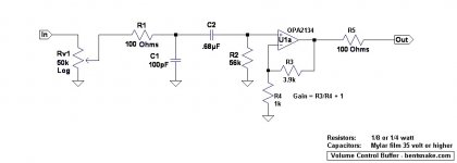
In for a penny, in for a pound, might as well put some gain on the table. Although I don't think you need any. You still have line-out feeding line-in, which is pretty much what you shoot for.
Circuit notes:
The input circuit remains unchanged from before. The OPA2134 has very high input impedance, so you can pretty much go wild with the input circuit.
U1a is now an amplifier, not a buffer. But the same comments as before apply due the high input impedance.
The circuit as shown has a gain of about 5, note the gain formula on the circuit diagram. You probably don't need this much, or any, but having it won't hurt anything, just turn down the volume--which after all is the point in the first place.
.
Attachments

Hi,
Without a sensible detailed description of the OP's set up,
its impossible to suggest how to move it on, if at all.
rgds, sreten.
Without a sensible detailed description of the OP's set up,
its impossible to suggest how to move it on, if at all.
rgds, sreten.
I generally like the circuit rec above, but it's also important to have 0.1uF (value not critical) power supply bypass caps within an inch of the opamp chip (closer is better), and to have a 100 - 200 ohm series resistor at the output of the whole circuit (outside of the feedback loop) to minimize the reactive effects of the load on the phase margin of the opamp circuit.
The value of the volume pot depends on what the source impedance is and what coupling cap it has at its output. 10K appears to be the smallest value that is recognized by the industry in general. I usually use a 50K, which will be a tiny bit noisier, but just to be sure I'm not rolling off the bass or over loading whatever opamp is inside the DAC chip or any other source I select. The passive Rf filter at the input is particularly wise, especially when the source is digital. Most circuits don't include that, and then they are asking the opamp to do something it can't do well, resulting in "transistor sound". Oh, and I'd use polypropylene or polystyrene caps if possible in the signal path (power supply bypass can be ceramic). Panasonic, Solen or any other cheap ones are fine. Expensive caps (more than $5 for a 1uF) are for suckers IMO.
The value of the volume pot depends on what the source impedance is and what coupling cap it has at its output. 10K appears to be the smallest value that is recognized by the industry in general. I usually use a 50K, which will be a tiny bit noisier, but just to be sure I'm not rolling off the bass or over loading whatever opamp is inside the DAC chip or any other source I select. The passive Rf filter at the input is particularly wise, especially when the source is digital. Most circuits don't include that, and then they are asking the opamp to do something it can't do well, resulting in "transistor sound". Oh, and I'd use polypropylene or polystyrene caps if possible in the signal path (power supply bypass can be ceramic). Panasonic, Solen or any other cheap ones are fine. Expensive caps (more than $5 for a 1uF) are for suckers IMO.
Last edited:
You may want to look at the second post in this thread. Nelson's subjestion is super
easy.
http://www.diyaudio.com/forums/pass-labs/103050-jfet-boz.html
easy.
http://www.diyaudio.com/forums/pass-labs/103050-jfet-boz.html
.
<< have a 100 - 200 ohm series resistor at the output of the whole circuit (outside of the feedback loop) to minimize the reactive effects of the load on the phase margin of the opamp circuit >>
I agree, and this becomes critical when, as now, the following circuit is unknown. I just plain forgot about those, but herewith correcting that, and I'm glad you said something.
Your other points are certainly valid, but I consider that decoupling/bypass capacitors--or other capacitor affairs--will be discussed when/if the subject arises. Or if not, then not, and it won't be the end of the world. In my opinion, around here the KISS rule is paramount.
.
Attachments

Last edited:
- Status
- Not open for further replies.
- Home
- Source & Line
- Analog Line Level
- Recommendations for a simple, opamp-based low-gain stage?