Hi guys!
I would to recapping this old recapping stabilized current power supply from a vintage amplifier.
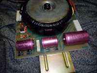
As you can see in the picture, there are three pink electrolitycs capacitors: the smallest ones are 3300uF 25 V, whilst the biggest one is 6000uF 32V.
I would to replace them with three capacitors with a bigger capacitance...but I repeat, it's a stabilizer current power supply board.
As I always say here, I'm just a newbie...so my question is: is this capacitors up-grade possible or could it a problem in a similar stabilizer current circuit board?
Thank you for your patience and kindness
Regards!
I would to recapping this old recapping stabilized current power supply from a vintage amplifier.
As you can see in the picture, there are three pink electrolitycs capacitors: the smallest ones are 3300uF 25 V, whilst the biggest one is 6000uF 32V.
I would to replace them with three capacitors with a bigger capacitance...but I repeat, it's a stabilizer current power supply board.
As I always say here, I'm just a newbie...so my question is: is this capacitors up-grade possible or could it a problem in a similar stabilizer current circuit board?
Thank you for your patience and kindness
Regards!
Attachments
I would say you need to have RLC (ESR) meter make some measurements prior to do some conclusion.
I really don't see a reason to do something with a device if I can't clearly see a real picture.
I really don't see a reason to do something with a device if I can't clearly see a real picture.
I would say you need to have RLC (ESR) meter make some measurements prior to do some conclusion.
I really don't see a reason to do something with a device if I can't clearly see a real picture.
It's from an amplifier from 1976...it's very old, so a recapping will be necessary!
Please, give me your opinion about the old capacitors replacement with some of bigger capacitance😉
Thank you in advance.
Regards.
What's that?
Jan
It's a power supply unit with current stabilizer from a very old amplifier (about 1976/1977).
😉
Regards.
I would say you need to have RLC (ESR) meter make some measurements prior to do some conclusion.
I really don't see a reason to do something with a device if I can't clearly see a real picture.
Attachments
I guess that means 'regulated'. (In many languages term 'regulated' sounds exact like 'stabilized', that's why it is easy to confuse).What's that?
Please, give me your opinion about the old capacitors replacement with some of bigger capacitance😉
I usually start from searching for a schematics. Otherwise I can only guess.
And I'm experienced with old Soviet capacitors, but have very approximate knowledge about foreign ones. That's why my guesses will be very inaccurate or of a very general type.
Last edited by a moderator:
Look for 105 C rated caps, a 'general purpose' type.
You wan't find nowadays large axial capacitors now (it is very unlikely they are exist), so prepare to find a decision how to mount radial ones to a PCB instead of axial. But there are still small axial caps on the market (<=100 uF). Sometimes there is a possibility to place radial caps vertical with just making a new hole for one pin.
Those orange caps are likely tantalum (or of a similar solid-capacitor type) and usually work very long and don't have to be replaced.
As I see from a first photo there are only three large axial caps can be 'recapped'. They have not a large capacitance and quite a small rated voltage so it has to be quite easy to find a substitute for them. Actual caps are usually a bit smaller then old ones, this may help too.
Last edited:
Yes, it is possible. To it wasn't problems, look for a 'general type' caps for a substitute. For example, a Low-ESR type caps can (in theory) make problems with stability.: is this capacitors up-grade possible or could it a problem in a similar stabilizer current circuit board?
Yes, of cause. I don't quite understand why my answers were to Jan but not to Peters8. It seems I've confused something. I'm sorry.Jan did not say what have attributed to him in the quotes in post #10. That was said by Peters8
(Unfortunately, I can't edit those my posts already now).
Last edited:
Yes, of cause. I don't quite understand why my answers were to Jan but not to Peters8. It seems I've confused something. I'm sorry.
(Unfortunately, I can't edit those my posts already now).
I've fixed it 🙂 and I don't know how you managed that either 😉
I guess that means 'regulated'. (In many languages term 'regulated' sounds exact like 'stabilized', that's why it is easy to confuse).
But what's that 'current stabilized' thing then? A constant current source?
Jan
Look for 105 C rated caps, a 'general purpose' type.
You wan't find nowadays large axial capacitors now (it is very unlikely they are exist), so prepare to find a decision how to mount radial ones to a PCB instead of axial. But there are still small axial caps on the market (<=100 uF). Sometimes there is a possibility to place radial caps vertical with just making a new hole for one pin.
Those orange caps are likely tantalum (or of a similar solid-capacitor type) and usually work very long and don't have to be replaced.
As I see from a first photo there are only three large axial caps can be 'recapped'. They have not a large capacitance and quite a small rated voltage so it has to be quite easy to find a substitute for them. Actual caps are usually a bit smaller then old ones, this may help too.
Thank you so much Vovk Z!
Just a last important question: have I to keep the capacitance/voltage of the original caps or can I replace the two original 3300uF 25 V cap with two new 4700uF 35V caps and the original 6000uF 32V cap with a new 6800 uF 40V (or 50V) cap?
I'm so sorry, I know I'm annoying you but I'm so confused about this thing😕
Thank you again for the precious support!😉
Regards
It is ok to increase a capacitance or rated voltage a bit. You may use 4700 uF 25-35V instead of 3300 uF 25 V, as well as it is totally fine to use 6800 uF 35-50V instead of 6000 uF 32 V.have I to keep the capacitance/voltage of the original caps or can I replace the two original 3300uF 25 V cap with two new 4700uF 35V caps and the original 6000uF 32V cap with a new 6800 uF 40V (or 50V) cap?
To be sure I would measure real voltages across them.
I don't want to guess because I'm not sure TS itself knows definitely.But what's that 'current stabilized' thing then? A constant current source?
It is ok to increase a capacitance or rated voltage a bit. You may use 4700 uF 25-35V instead of 3300 uF 25 V, as well as it is totally fine to use 6800 uF 35-50V instead of 6000 uF 32 V.
To be sure I would measure real voltages across them.
Thank you again VovK Z: I've done what you've recommended to do: measuring the voltage across the pink caps with my multimeter setted on AC: on the two 3300uF 35V caps I measured 18 V whilst on the bigger pink 6000uF 32V cap, I measured 20 V.
So you have the final decision on this operation😉
Thank you for your patience and kindness, my friend!

Regards!😉
mio amico Digi-key says you're in luck on the smaller ones, but you'll either have to replace the larger with a radial or run two of the smaller ones in parallel. Since Vovk is saying too low of an ESR is actually a problem then the latter option is probably not a good idea in this case.
40V/3900uF/105Deg polar axial:
https://api.kemet.com/component-edge/download/specsheet/PEG130KL4390Q.pdf
40V/3900uF/105Deg polar axial:
https://api.kemet.com/component-edge/download/specsheet/PEG130KL4390Q.pdf
- Home
- Amplifiers
- Power Supplies
- Recapping a stabilized current power supply!