Hi All,
I have an old B&O Beomaster 3000 type 2402, which I love but it has a few problems - one channel dropping out randomly, very scratchy sliders etc.
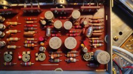
I was going to recap the whole thing, but the old electrolytics look ok, no leaks, they are solid ROE types, see photo. But their measured values seem way off nominal - e.g. the 100/35 measured 149 uF, others were similarly off. Does this mean they need replacing?
Thanks for any advice - or if anyone could point me to a B&O repair forum?
Theo
I have an old B&O Beomaster 3000 type 2402, which I love but it has a few problems - one channel dropping out randomly, very scratchy sliders etc.
I was going to recap the whole thing, but the old electrolytics look ok, no leaks, they are solid ROE types, see photo. But their measured values seem way off nominal - e.g. the 100/35 measured 149 uF, others were similarly off. Does this mean they need replacing?
Thanks for any advice - or if anyone could point me to a B&O repair forum?
Theo
Attachments
Must have hit the wrong button there.
Scratchy pots can usually be fixed with a good clean with deoxit or similar product.
With channel dropping out I found a couple of bad solder joints on some of my B&O stuff.
Scratchy pots can usually be fixed with a good clean with deoxit or similar product.
With channel dropping out I found a couple of bad solder joints on some of my B&O stuff.
Hi All,
I have an old B&O Beomaster 3000 type 2402, which I love but it has a few problems - one channel dropping out randomly, very scratchy sliders etc.
I was going to recap the whole thing, but the old electrolytics look ok, no leaks, they are solid ROE types, see photo. But their measured values seem way off nominal - e.g. the 100/35 measured 149 uF, others were similarly off. Does this mean they need replacing?
Thanks for any advice - or if anyone could point me to a B&O repair forum?
Theo
Theo, and all the rest of you on here, I have to yet again educate the "online" masses.....
Visual inspection of a capacitor to "see if it's leaking" is nonsense, because asides from fluid actually leaking from it, it can also be "leaky" electronically.
That means it allows DC to pass through it, causing issues with the equipment.
And the only sensible way to determine that is by measuring voltages with a meter, or other test equipment.
Whenever I see a person stating a visual inspection, I have to open my mouth (keyboard).
Bottom line, you cannot determine such things visually.
As for "off value" - it "can" be a clue to deterioration of the capacitor.
Because when the electrolyte dries up due to age, capacitance can actually go UP, bring the "plates" closer together internally.
Well, that amplifier is original and old enough (1970) to be using carbon composition resisitors. Sadly, ROE caps don't have a good reputation and no electrolytic is going to last 50 years whether in use or not. Just replace all the electrolytics with a good quality brand/grade, taking note that modern caps are much smaller and probably have different lead spacings and types of pins. Check the manufacturer's datasheets which are available from their websites or a distributor's listings.
All that fails on these well designed amplifiers is the pre set pots, they get tarnished and can go open circuit causing overheating and in some cases intermittent cutting out plus the sliders could do with a clean with Electrolube Switch Cleaner as can the switch contacts.
I recently had a B&O 2000 in for service, even older than the 3000. I removed the electrolytics to test the ESR and leakage values and found yet again they were almost as good as new with exception to the main smoothers and speaker coupling capacitors. Good fun trying to source the correct size and had to use slightly smaller physical sizes but always with the same values.
NEVER purchase NOS capacitors, it always ends in tears and extra faults!
You can't tell if a capacitor is OK by looking at it. Rising capacitance values typically mean the oxide layer is thinning out, so the voltage capability and (electrical) leakage will likely be much worse than original. Testing leakage requires unsoldering one terminal anyway, probably best to replace them and give the unit another few decades of life expectancy.I was going to recap the whole thing, but the old electrolytics look ok, no leaks, they are solid ROE types, see photo. But their measured values seem way off nominal - e.g. the 100/35 measured 149 uF, others were similarly off. Does this mean they need replacing?
You can't tell if a capacitor is OK by looking at it. Rising capacitance values typically mean the oxide layer is thinning out, so the voltage capability and (electrical) leakage will likely be much worse than original. Testing leakage requires unsoldering one terminal anyway, probably best to replace them and give the unit another few decades of life expectancy.
Indeed, all that, as I mentioned previously in my post.
Reliability is key here, age takes its toll on everything.
Thanks a lot for all the right statements, the above linked forum don´t accept any
deviation from their idea of the original state, however wrong it may be...
Some serious questions about the BM 3000 amplifier:
Today, 3 modern 18mF/80V will solve most of the classical problems with AC-coupling:
such as distorsion and current capacity (low ESR), of course the bridge must be replaced in order to cope with the surge (no NTC soft start) but the overall impedance will be lower.
The output stage has std. 2N3055 (60V) so they will hold (SOA), but what can be done to limit the losses (heat) in the power stage at full load?
i. e what should I look out for in order to obtain maximum power output?
Amplifer bias setting - adjusting for the proper idle current of the outputs, per service manual information. As for heat "losses", that's normal in amplifiers when driven at loud volume. Home amplifiers were not designed for continuous loud use. People that insist on loud music in the home or outdoors should buy a high powered commercial amp with speakers to match.Thanks a lot for all the right statements, the above linked forum don´t accept any deviation from their idea of the original state, however wrong it may be...
Some serious questions about the BM 3000 amplifier:
Today, 3 modern 18mF/80V will solve most of the classical problems with AC-coupling:
such as distorsion and current capacity (low ESR), of course the bridge must be replaced in order to cope with the surge (no NTC soft start) but the overall impedance will be lower.
The output stage has std. 2N3055 (60V) so they will hold (SOA), but what can be done to limit the losses (heat) in the power stage at full load?
i. e what should I look out for in order to obtain maximum power output?
I have just inherited another BM3000, thus the reason to investigate it further,
as the build quality, transformer och power stage (cooling) is underrated.
I found that the single ended supply voltage at most will be 45VAC at max
therefore 63VDC capacitors will work just fine for both PSU and output at
15mF which is cheap (Nichicon SMH). Both (PSU & tuner) bridge rectifiers are
degraded and MUST allways be replaced. No expensive 80V or 100V capacitors
are justified in anyway.
The amp uses std. 2N3055 but the emitter resistors are 0,15/1W and was replaced
with 0,1/5W to start with. The first series where 30W, then 40W (all at 4 ohms)
Should it not be possible to push it to 50W ? (Still at 63VDC single rail voltage)
There is a great interest in pushing the output of these amps, as BM4000 uses
the same setup, but darlington pairs in order to obtain 60W output (at 70VDC).
Those B&O's were designed foremost to be "stylish" and used at reasonable volume levels in a home setting.
"Pushing" things such as amp power isn't wise, and since the heat elimination properties are not the best, it's asking for trouble.
It simply wasn't designed for it.
I mean, look at the cabinet, it's got no place for big honkin' heatsinks.
The "great interest" mentioned is typical internet babble that I've heard so many times, and those people need to get a life, and stop trying to milk blood from a stone.
Why then was/is the BM4400 (75 WPC at 4 ohm) so popular?
(Heralded as one of B&O´s foremost amplifier in the past, not being AC-coupled.)
The BM3000, 30W. BM3000-2, 40W. BM4000, 60W and the BM4400 (above)
all use the same chassis with small differences in single rail voltage (not BM4400).
The BM3000 was the most produced and therefore the most available, the rest being
much more scarce and thus expensive, even today as second hand units.
In those days they where frown upon being AC-coupled, but today this not a problem.
50, 60 or 75W are still moderate power outputs which the chassis (transformer and
output stage/frame) can, in fact, handle. (The old BM1400 had solid casting frame and
a double cooling frame built like a tank.) Otherwise, just as you mentioned, they where
"stylish" and nominally built, I fully agree. But this is NOT the case here. The BM3000
can be brought up in power to what the 63VDC will allow. Now that is the question.
(This was done in BM3000-2 to 40W, but why not to 50W?)
Before making these statements, examine the fact and you will see that the BM3000 (remove the grille) has prepared holes (fittings) for external heatsinks (4) and drawn
out external sensors (both sides) for enhanced output should you wish to use it,
just as provided in the BM4000 series, without the need for fans (power tap provided).
The four 2N3055 has a lot of power reserve (SOA) left to provide more current.
You are of course limited to the 63V rail (30V over each transistor) can provide.
- Home
- Amplifiers
- Solid State
- ReCap on old B&O Beomaster 3000