Hi,
I started my first tube amp project and decided to go for a 10W PP.
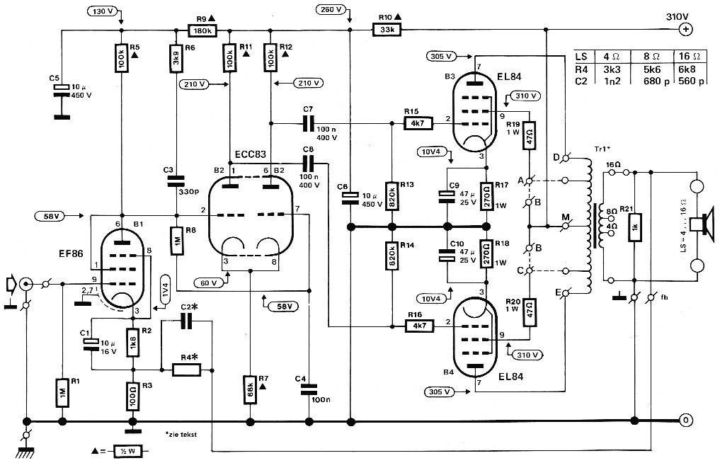
I have a schematic from the magazine "Elektor".
It look a lot like the Mullard 5-10.
I started ordering all the components, and the transformers just arrived.
They are from Amplimo, 8k 0-4-8 ohm.
Someone noticed me that the feedback resistor+capacitor (C2 and R4) should be connected to the 16ohm side (at least the way they are calculated in this circuit). I first thought the feedback circuit (C2 and R4) should always be connected to the output the speakers use... But no...
So my question is: how can I recalculate the feedback circuit so that I connect this circuit to the 8ohm primary AND my speakers to the 4ohm primary?
I know some basic electrics but not at this level... I would highly appreciate your help.
Thanks!
Regards
I started my first tube amp project and decided to go for a 10W PP.
I have a schematic from the magazine "Elektor".
It look a lot like the Mullard 5-10.
I started ordering all the components, and the transformers just arrived.
They are from Amplimo, 8k 0-4-8 ohm.
Someone noticed me that the feedback resistor+capacitor (C2 and R4) should be connected to the 16ohm side (at least the way they are calculated in this circuit). I first thought the feedback circuit (C2 and R4) should always be connected to the output the speakers use... But no...
So my question is: how can I recalculate the feedback circuit so that I connect this circuit to the 8ohm primary AND my speakers to the 4ohm primary?
I know some basic electrics but not at this level... I would highly appreciate your help.
Thanks!
Regards
The voltage at the 8 ohms tap is 1/2 the voltage on the 16 ohms tap. To keep the same feedback factor you need to halve the feedback impedance.
That means half R4 and twice C2.
But why do you ask this? It is shown in the schematic.
Jan
That means half R4 and twice C2.
But why do you ask this? It is shown in the schematic.
Jan
You see the chart top right next to the 310V B+? That says what to use for each tap.
The calculated difference between 16 and 8 ohms would be a factor of .707. Provided values are more like guidelines based on commonly available parts values.
The calculated difference between 16 and 8 ohms would be a factor of .707. Provided values are more like guidelines based on commonly available parts values.
Oh noThe voltage at the 8 ohms tap is 1/2 the voltage on the 16 ohms tap. To keep the same feedback factor you need to halve the feedback impedance.
That means half R4 and twice C2.
 The voltage on the 4Ω tap is half the voltage on the 16Ω tap.
V²=P.R with P=10W V=√160=4√10 for 16Ω out and V=√40=2√10 for 4Ω out.

Mona
I was assuming the feedback circuit should always be connected to the 16ohm side, no matter if your speaker is connected to the 4, 8 or 16 side...
So this is incorrect?
If I use the 4ohm output for the speakers the feedback circuit should go on the 4ohm side too and with the values in the schematic (top right)?
This is not clear to me from the schematic ...
So this is incorrect?
If I use the 4ohm output for the speakers the feedback circuit should go on the 4ohm side too and with the values in the schematic (top right)?
This is not clear to me from the schematic ...
You would put the feedback on the 4 ohm tap if using a 4 ohm load and use the 4 ohm RC values. May not make a big difference. Some amplifier manufacturers do not bother with it.
The signals at the several taps are 99.9% the same except the ratio leverage. Connecting to the SAME tap as the load is not necessary until EVERY other frill has been designed in (i.e. never).
Oh no
V²=P.R with P=10W V=√160=4√10 for 16Ω out and V=√40=2√10 for 4Ω out.
Mona
Of course. I stand corrected.
Jan
Ok, great!
Thanks for the feedback 😀
So I'll use the values for 4ohm and just connect the feedback circuit to the 4ohm too.
Thanks for the feedback 😀
So I'll use the values for 4ohm and just connect the feedback circuit to the 4ohm too.
If the output transformers are not original as I suspect it is useless to use those values for optimum performance ...
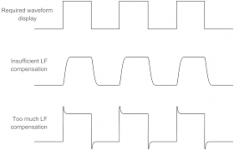
You have to figure out how much NFB you need ( resistor ) and after that with a scope find the right value capacitor for clean 1KHz square waveform .
You have to figure out how much NFB you need ( resistor ) and after that with a scope find the right value capacitor for clean 1KHz square waveform .
Last edited:
There is information on internet and diyaudio if you search .
Personally I would use a NFB resistor that will decrease by 2 the sensitivity ( lets say from 250mV to 500mV ) , thats about 6dB of negative feedback . I don't know if the amount for Elektor schematic is provided somewhere . If bandwidth is not sufficently flat you could use more
The value of the capacitor in parallel is chosen to have a 1 KHz square wave as perfect as possible , without overshoot ( tendency for oscillation ) or undershoot ( attenuation of audio high frequency ) .
Very similar to compensation of scope probes ... I think you know what I'm talking about .
Attachments
Last edited:
- Home
- Amplifiers
- Tubes / Valves
- Recalculate feedback circuit