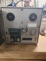
Hi, I found a broken akai 1700 reel to reel player at the local thrift store for the crazy prize of $5.
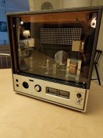
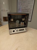
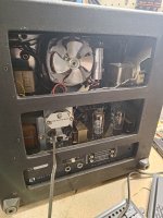
I ripped everything out and dismantled most of it and rebuilt it as a two channel amplifier for my office.
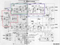
Now, I kept the VU-meters and after checking the schematic in the service manual I found online I drew the conclusion that it should only be a matter of connecting the VUs parallel with the speaker outputs and use a 10k resistor to ground..
This doesn't work.
I have read that some have integrated diodes and parts and since the schematic doesn't show these I drew the conclusion that the meters had them integrated.
So, could someone have a look or point me in the right direction?
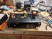
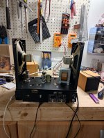
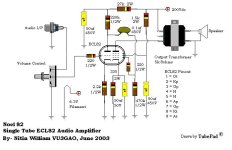
I'll attach original schematic, new schematic and some pictures of the build.


Last edited:
From the schematic, it looks like the meters are across the headphone output, so they should have the built in diodes. 10K series R looks way too big. Try 1K and see if you get pointer movement - then play around as necessary. Best!
Yeah, but it is connected between the ground and the secondary side of the output transformer, shouldn't that be the same as the speaker output?From the schematic, it looks like the meters are across the headphone output,
The voltage swing on the headphone OPT could be higher than you might imagine and the 200 ohm series feeds to headphone back that up.
Passive meters even using germanium diodes are pretty insensitive to low amplitude signals.
Passive meters even using germanium diodes are pretty insensitive to low amplitude signals.
First thing you need to do imo is test the meters in isolation with a known AC voltage source which can be from any amp, valve or transistor. Transistor is ideal because it is safe with no load.
Just connect the meter across the speaker output and crank the level up until the meter reads 0DB while measuring the signal needed to do that. Using a 400Hz or thereabouts signal means 99% of DVM's will give an accurate AC voltage reading. You then have an idea of what signal levels the meters expect to see.
You mention about not being certain if the meter includes diodes... typically a passive VU circuit looks like this and historically germanium diodes would be used because of the much lower forward volt drop. So maybe you are on to something there if there appears to be no extra circuitry.
So, dig out that old midi-system from the cellar and pop in a cd.
Put the meter between the outputs, without speaker connected, start to play at a low volume (or use aux input and 400Hz signal).
Up the volume until they wake up and measure AC across speaker output?
Put the meter between the outputs, without speaker connected, start to play at a low volume (or use aux input and 400Hz signal).
Up the volume until they wake up and measure AC across speaker output?
If there are diodes in there they should only deflect in the one direction.
Something I thought of afterwards... and that if there were a bridge rectifier present (which is not normal for a passive VU meter circuit as you have double the volt drop to overcome) then the meter deflection would be the same irrespective of battery polarity.
- Home
- Amplifiers
- Tubes / Valves
- Rebuilt Reel to reel, Help with VU-meters