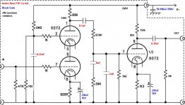
I've been working lately on my friend's AN kit's L3 phono stage. He bought it used . In the RIAA network, caps are slightly off the values needed. These are nice Jensen Copper PIO caps ($$$) and I'd like to keep them. So instead of 8n2 and 2n8 values needed I have ~8n7 and 2n4. How should I correct the resistors to get the same RIAA curve ?
TIA . L
TIA . L
Attachments
I would. There are some good RIAA Calculators on -line Google for one.
Don't forget to add in the Source Impedance which will be just less than that 82K, calc for yourself but my quick and dirty calcs suggests about 75K5 (assumed 6072 = 12AY7, rp = 22K8, mu = 40).
You can also mod the circuit slightly to put a resistor in series with that 2n8 and shift the take off point to that junction to do the extra 50KHz corner (3.18us) which Alan Wright talked about here (Note 4 pg 1):
http://www.vacuumstate.com/fileupload/SP_15_Article.pdf
I did this on a SS phonostage and the difference was quite noticeable. Have'nt tried it on a tube phono (cause I don't have one).
The more accurate the RIAA the better it will sound.
Cheers,
Ian
Last edited:
The caps need a ratio of 2.916 (remembering to include Miller capacitance).
The bigger cap with its series resistor must have a time constant of 318us
The smaller cap with the total source resistance must have a time constant of 750us.
Don't waste your time with Alan's 50kHz pole, it's a pointless fallacy.
The second stage should have a gain of about 35 making a Miller capacitance somewhere around 55pF. If you use you 8n7 cap then you would need 8.7/2.916 - 0.055 = 2.92nF for the smaller cap. Since you only have 2n4, you need an extra 520pF in parallel with the second cap.
Last edited:
In this type of RIAA network you must maintain the correct component values. Change any component and you must change all the other values to maintain the correct proportions. The values on the schematic were chosen for availability (standard values) rather than strict accuracy. A quick search will direct you to a few online RIAA calculators if you want the theoretically correct values.
The main issue you have is the ratio of your capacitor values is not ideal. For accuracy you will need to parallel another small cap with the 2n4, because 3nF is the correct match for 8n7. With those values you can substitute 252K and 36.5K resistors.
edit:
Accounting for the Miller capacitance, per Merlinb, indicates that 2.9nF is a closer match than 3nF. Parallel a .47nF or .56nF with the 2n4.
Last edited:
Thank You guys. I found Kab Riaa calculator and Steve is right . To use 8n7 I will have to change 270k to~250k and 39k to ~36K and parallel 2n4 with 470pF.
Experimenting with the circuit I have to say that those caps do have big impact on the sound. I don't understand why the first stage B+ is not decoupled from the second one with RC filter ? In most elaborate ( expensive components) incarnation this exact circuit boards costs thousands of $$$ so cost saving on one resistor and 20-100uF cap is unlikely to be a reason but maybe it is?
Experimenting with the circuit I have to say that those caps do have big impact on the sound. I don't understand why the first stage B+ is not decoupled from the second one with RC filter ? In most elaborate ( expensive components) incarnation this exact circuit boards costs thousands of $$$ so cost saving on one resistor and 20-100uF cap is unlikely to be a reason but maybe it is?
How does one measure with that kind of precision? My $250 multi meter has at least 1nF cable capacity, depending on the handling.
You need a unit with calibration to compensate I'd guess. I have BK precision 875B LCR meter and its a nice little thing ..How does one measure with that kind of precision? My $250 multi meter has at least 1nF cable capacity, depending on the handling.
You use really, really short cables, or shove the components right into the sockets with no cables at all.How does one measure with that kind of precision? My $250 multi meter has at least 1nF cable capacity, depending on the handling.
For 8.7nF you can use 8.2nF polyester + 510...560pf if you find styroflex would be nice. Also for 2.4nF you can use 2.2nF polyester + 220pF styroflex or 2*1.2nF in parallel.
Trimis de pe al meu LG-P760 folosind Tapatalk
Trimis de pe al meu LG-P760 folosind Tapatalk
Don't use ceramic caps because they are not good for a hi-fi system. They have leakage and they get easy 'wet' and change values at temperature and even after soldering.
Trimis de pe al meu LG-P760 folosind Tapatalk
Trimis de pe al meu LG-P760 folosind Tapatalk
Ceramics caps are rarely leaky, but high value ceramics can be non-linear and temperature sensitive. OK for decoupling, but not filter networks. Low value ceramics are fine.
Sent from my Dell laptop using XP and Firefox
Sent from my Dell laptop using XP and Firefox
Why trying, if you can affort 'm use 'm! 😀
I've seen charts comparing dielectric losses, that would probably be a theoretical exercise in this filter? Styroflex once was best (in terms of loss, stability and precision) for this kind of application. Large army surplus caps based on PTFE dielectric probably won't bring advantage here because of their size, introducing inductance?
I've seen charts comparing dielectric losses, that would probably be a theoretical exercise in this filter? Styroflex once was best (in terms of loss, stability and precision) for this kind of application. Large army surplus caps based on PTFE dielectric probably won't bring advantage here because of their size, introducing inductance?
- Status
- Not open for further replies.
- Home
- Amplifiers
- Tubes / Valves
- Re- calculating RIAA network