Hello everyone!
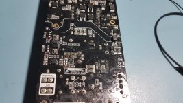
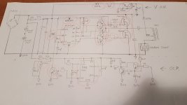
I am having issues with an RCF amplifier SMPS. When switched on, the power supply mosfets (P20NM60) always going to short-circuit or exploding, sometimes killing the gate driver circuit, the driver ic (S21531D) and the short circuit protection part. I measured all the passive and remaining active components around it, and it seemed good. I checked the secondary side and there is no short circuit. The primary DC bus ok, around 310V. So I replaced the faulty components, the driver ic, the mosfet driver circuit, and the mosfets. But I didn't succeed, the mosfets became short-circuited again. So I tried to redraw the schematic of the primary side. Sorry for the poor drawing!
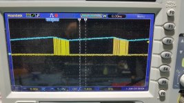
I replaced again the control ic, the entire gate drive circuit, the control ic's auxiliary and main power supply voltage regulator circuit, and the LMC555CM timer ic, which is part of the short circuit protection circuit. Almost everything, except for a few resistors and capacitors... (The replaced components are marked in red) So I started the power supply connected in series with a light bulb for current limitation, but first without mosfets and I checked the bottom mosfet gate control signal on an oscilloscope. It seemed good, the frequency was 100kHz and after a few cycles it breaks and restarts, which is understandable, since the control ic only receives voltage from the starting power supply, which does not provide enough current for continuous operation. I soldered in the new mosfets, but no succes. The mosfets goes into complete short circuit again. 😕
I was curious that there was no short circuit in the primary winding of the transformer. I measured the inductance of the primary winding in the circuit, which was 1.95mH. So I don't think the transformer is shorted.
What could be causing the problem?🤔 Has anyone encountered a similar phenomenon?
If you have any suggestions, I'd be happy.
Best regards!
I am having issues with an RCF amplifier SMPS. When switched on, the power supply mosfets (P20NM60) always going to short-circuit or exploding, sometimes killing the gate driver circuit, the driver ic (S21531D) and the short circuit protection part. I measured all the passive and remaining active components around it, and it seemed good. I checked the secondary side and there is no short circuit. The primary DC bus ok, around 310V. So I replaced the faulty components, the driver ic, the mosfet driver circuit, and the mosfets. But I didn't succeed, the mosfets became short-circuited again. So I tried to redraw the schematic of the primary side. Sorry for the poor drawing!
I replaced again the control ic, the entire gate drive circuit, the control ic's auxiliary and main power supply voltage regulator circuit, and the LMC555CM timer ic, which is part of the short circuit protection circuit. Almost everything, except for a few resistors and capacitors... (The replaced components are marked in red) So I started the power supply connected in series with a light bulb for current limitation, but first without mosfets and I checked the bottom mosfet gate control signal on an oscilloscope. It seemed good, the frequency was 100kHz and after a few cycles it breaks and restarts, which is understandable, since the control ic only receives voltage from the starting power supply, which does not provide enough current for continuous operation. I soldered in the new mosfets, but no succes. The mosfets goes into complete short circuit again. 😕
I was curious that there was no short circuit in the primary winding of the transformer. I measured the inductance of the primary winding in the circuit, which was 1.95mH. So I don't think the transformer is shorted.
What could be causing the problem?🤔 Has anyone encountered a similar phenomenon?
If you have any suggestions, I'd be happy.
Best regards!
Attachments
I would suggest that you probe the output voltage from the half-bridge and check (also replace if necessary) the series capacitor to the transformer. If everything is OK and the short circuit protection still trips, then it could be due to "flux walking" within the transformer (best guess).
The topology is half-bridge, but what about the control method? Is it voltage-mode, series resonant or open-loop (50% fixed duty) ? Either way there should be a zero average voltage (pulse-width) presented to the transformer's primary winding, failing which there'd be flux buildup and consequent over-current tripping.
The topology is half-bridge, but what about the control method? Is it voltage-mode, series resonant or open-loop (50% fixed duty) ? Either way there should be a zero average voltage (pulse-width) presented to the transformer's primary winding, failing which there'd be flux buildup and consequent over-current tripping.
As drawn it looks like the circuit depends strongly on the start up times of the 555 current limiter and the 21531 ICs. You have 240K and 100uF (555) and 440K/47K and 10uf (21531). The 21531 also has a startup current that will mess about with things and it is anyones guess as to what the 555 and its associated bucket of guess work will think it is doing.
Yes, I think it is slightly horrorshow. Basically you only use a 555 if you want to make old style synthesizer burps and farts. You don't want an SMPS that does the same but much much louder.
If your 21531 starts up before your 555 then it will dump serious amounts of current into the supplies output capacitors and, without the 555, whatever it thinks it is doing when it is awake, active will kill itself. Seriously looking at some of the time constants I get the impression that some idiot messed about with bad stuff until a few worked and then put it into production.
Otherwise check that your 240K/480K resistor chains have the right values, in particular the 240K chain. 310V across 240K is 0.4W and surface mount resistors of a certain size are, if I recall, rated at 200mW (200mW+200mW=400mW) so that might be pushing things. If they have gone high value then your 555 will not wake up in time.
The weirdest fault I had with an SMPSU was a couple of polyester film caps that had a high ESR at 100kHz, like a leaky electrolytic.
They measured fine on the capacitance range of a Fluke multimeter.
I suspect you have something similar, that measures fine with the instruments you have, but is actually faulty.
They measured fine on the capacitance range of a Fluke multimeter.
I suspect you have something similar, that measures fine with the instruments you have, but is actually faulty.
I also think you need to check the BJTs used to trigger the 555 and the passives around it, just to make sure that your protection tripping is indeed genuine and not a false one.
This won't work. Top tip for idiots who want to use a 555 and some wibbly wobbly transistors along with a bucket load of drivel. Don't do that. Do this.

Of course you will use an LM393 to get the quiescent current down and read the datasheet and leave out R3. Supply it from the same supply as your 21531 and make your start up bias chain cope with the, about, 450uA current to get things going. 2 X 300K (80mW per resistor) and 22uF should do it.

That's a 400nS Comparator Delay and 14% error in your limit. The 21531 has a 350nS shutdown delay so that will double it to 30%. If you are precious then adjust R1 or R2.
Again I could be wrong but it would seem there is no reason to rip off someone else's 555 failure and place it in your own production product and upset your customers when they blow up.
Oh. Just to add. It's still Game Over if you are the sort of cheapskate wang who does not include output filter inductors on a half-bridge or similar SMPS because that didn't work for all the other idiots.
Of course you will use an LM393 to get the quiescent current down and read the datasheet and leave out R3. Supply it from the same supply as your 21531 and make your start up bias chain cope with the, about, 450uA current to get things going. 2 X 300K (80mW per resistor) and 22uF should do it.
That's a 400nS Comparator Delay and 14% error in your limit. The 21531 has a 350nS shutdown delay so that will double it to 30%. If you are precious then adjust R1 or R2.
Again I could be wrong but it would seem there is no reason to rip off someone else's 555 failure and place it in your own production product and upset your customers when they blow up.
Oh. Just to add. It's still Game Over if you are the sort of cheapskate wang who does not include output filter inductors on a half-bridge or similar SMPS because that didn't work for all the other idiots.
Last edited:
Yes, and also check the current-sense resistors to see if they've increased in value, triggering the protection.
Thank you all very much for the replies! Unfortunately, I haven't had time for it lately but I will make time for it again soon.
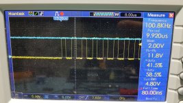
The control method is open-loop with fixed 50% duty. Yes, I checked the output of the half-bridge without a series capacitor and it was a nice clean 100kHz 320Vpp square wave with 50% duty cycle.I would suggest that you probe the output voltage from the half-bridge and check (also replace if necessary) the series capacitor to the transformer. If everything is OK and the short circuit protection still trips, then it could be due to "flux walking" within the transformer (best guess).
The topology is half-bridge, but what about the control method? Is it voltage-mode, series resonant or open-loop (50% fixed duty) ? Either way there should be a zero average voltage (pulse-width) presented to the transformer's primary winding, failing which there'd be flux buildup and consequent over-current tripping.
440k and 10uF for the 21531 and 240k and 100nF for the 555. In principle, the time constants are fine. Sorry for the poor drawing!As drawn it looks like the circuit depends strongly on the start up times of the 555 current limiter and the 21531 ICs. You have 240K and 100uF (555) and 440K/47K and 10uf (21531). The 21531 also has a startup current that will mess about with things and it is anyones guess as to what the 555 and its associated bucket of guess work will think it is doing.
Yes, I think it is slightly horrorshow. Basically you only use a 555 if you want to make old style synthesizer burps and farts. You don't want an SMPS that does the same but much much louder.
If your 21531 starts up before your 555 then it will dump serious amounts of current into the supplies output capacitors and, without the 555, whatever it thinks it is doing when it is awake, active will kill itself. Seriously looking at some of the time constants I get the impression that some idiot messed about with bad stuff until a few worked and then put it into production.
Otherwise check that your 240K/480K resistor chains have the right values, in particular the 240K chain. 310V across 240K is 0.4W and surface mount resistors of a certain size are, if I recall, rated at 200mW (200mW+200mW=400mW) so that might be pushing things. If they have gone high value then your 555 will not wake up in time.
I also thought of such a possible case.The weirdest fault I had with an SMPSU was a couple of polyester film caps that had a high ESR at 100kHz, like a leaky electrolytic.
They measured fine on the capacitance range of a Fluke multimeter.
I suspect you have something similar, that measures fine with the instruments you have, but is actually faulty.
- Home
- Amplifiers
- Power Supplies
- RCF amplifier SMPS mosfets keeps blowing