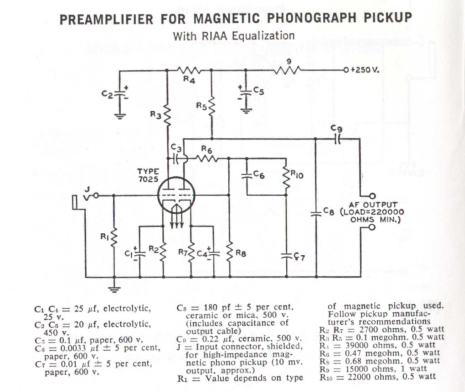
I have built the RCA tube manual RIAA phono preamp. Sounds great.
I am just wondering about the purpose of that last little 180pf cap on the anode of the second triode. The say to reduce it as you make the interconnect cable longer. Hopefully it isn't critical to the RIAA eq curve implentation.
I am just wondering about the purpose of that last little 180pf cap on the anode of the second triode. The say to reduce it as you make the interconnect cable longer. Hopefully it isn't critical to the RIAA eq curve implentation.
Last edited:
C6 and C7 would be setting the RIAA curve.
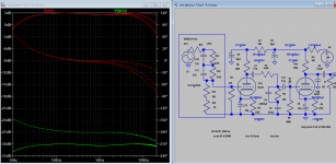
C8 would start cutting off above about 23Khz or higher depending on load.
Likely to keep RF or other higher frequency gremlins out.
C8 would start cutting off above about 23Khz or higher depending on load.
Likely to keep RF or other higher frequency gremlins out.
Eli has an improved version, hopefully he will stumble across this thread.
One of the problems with this design is it's designed to drive rather high impedances and is very sensitive to external capacitance on the output.
You could add a cathode follower at the output to address.
One of the problems with this design is it's designed to drive rather high impedances and is very sensitive to external capacitance on the output.
You could add a cathode follower at the output to address.
C6 and C7 would be setting the RIAA curve.
C8 would start cutting off above about 23Khz or higher depending on load.
Likely to keep RF or other higher frequency gremlins out.
Had a feeling that was what it might be for. Does it form a filter with the plate load and Rp of the valve. That comes out to about 23 kHz with them in parallel.
Thank you
Eli has an improved version, hopefully he will stumble across this thread.
One of the problems with this design is it's designed to drive rather high impedances and is very sensitive to external capacitance on the output.
You could add a cathode follower at the output to address.
Actually I have built a few of them now and when I build them as a standalone unit, yes I do add a cathode follower. The circuit sounds good either way.
Would like to see Eli's version. Link to a schematic?
It said "include capacitance of output cable", if the cable capacitance already added up to 180pf, I don't think you will need it, else the upper end will suffer.
In no instance am I using a cable. I am either feeding it direct to the next stage in an integrated preamp, or feeding it to a cathode follower when it's used in a standalone phono preamp. It probably isn't that necessary anyway, if, as discussed above, it's just to remove any high frequencies above the audible range. I haven't struck any stability problems with this circuit.
hotbottle wrote: "I have built the RCA tube manual RIAA phono preamp. Sounds great."
Is it possible (are you willing ) to publish your layout of this circuit?
Did you build it using "free wiring" or did you designe a printed circuit board for it?
Is it possible (are you willing ) to publish your layout of this circuit?
Did you build it using "free wiring" or did you designe a printed circuit board for it?
Eli has an improved version
I believe that is what this is.
Our build with over the top PS worked really well.
dave
Attachments
Eli has an improved version, hopefully he will stumble across this thread.
One of the problems with this design is it's designed to drive rather high impedances and is very sensitive to external capacitance on the output.
You could add a cathode follower at the output to address.
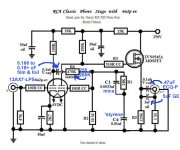
Found Eli's tweak here: valve phono stage on a budget
Attachments
hotbottle wrote: "I have built the RCA tube manual RIAA phono preamp. Sounds great."
Is it possible (are you willing ) to publish your layout of this circuit?
Did you build it using "free wiring" or did you designe a printed circuit board for it?
No need to publish the schematic. It is the same as the RCA one, with a cathode follower added at the end. All point to point, as you say, free wiring. I have never like circuit boards for tubes having worked on old TV sets where the boards were cooked and broken from mechanical leverage of heavy tubes.
See my next reply as well about Eli's circuit.
I believe that is what this is.
Our build with over the top PS worked really well.
dave
I see. He used a SS cathode follower. I used a triode. Yes, I think it performs well.
Found Eli's tweak here: valve phono stage on a budget
Thanks. I see, the C8 180pf cap is left off for both these circuits. I suspect, adding the 100R grid stoppers for stability is all it really needs.
No need to publish the schematic. It is the same as the RCA one, with a cathode follower added at the end. All point to point, as you say, free wiring. I have never like circuit boards for tubes having worked on old TV sets where the boards were cooked and broken from mechanical leverage of heavy tubes.
See my next reply as well about Eli's circuit.
It happened that I have quite a lot of experience with old TV sets and, apart of the power supply part on those PC boards (you are absolutely right when this part is the question), no part was "cooked and broken".
All my tube designs at this moment are using PC boards as a starting point.
All the best,
Joe.
Want to add :
"apart of the power supply part on those PC boards"
Especially the part where the line output transformer is placed on that board.
"apart of the power supply part on those PC boards"
Especially the part where the line output transformer is placed on that board.
I was wondering how critical the choice of tube has to be so that the RIAA equalisation is not disrupted? I have a box of 7B6 tubes, that are Loctal 6SQ7/6AV6, and the triode in the 6AV6 is close to one half of a 12AX7/ECC83.
Plate resistance 7B6 is 91k compared with 62.5K for the ECC83, otherwise the characteristics look similar. Both have 100 ampification factor. Curves are a close match.
I am conscious of the fact that phono amplifiers have a synergy between passives and tube characteristcs. Is it worth considering 6SQ7/7B6?
Last edited by a moderator:
Remember that rp (plate resistance) of a triode varies at different operating points.
A 12AX7 run with 0.5mA Ip (plate current) and Vpk (plate to cathode voltage) of 200V probably has rp of 90k ohms or so (guesstimate, I didn't draw loadlines).
However, that same 12AX7 run with 1mA Ip and Vpk of 125V will have much lower rp, probably around 70k ohms (guesstimate).
Are you comparing 7B6 and 12AX7 at identical operating points?
Unless the rp forms part of the RIAA filter network, it will make no difference. Here the RIAA network is passive, cap coupled from the first triode, and working into the high impedance of the second. I am wondering if the rp will have any, or much, effect at all.
- Home
- Amplifiers
- Tubes / Valves
- RCA tube manual phono preamp - what does the 180pf do?