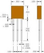
Does any one have a schematic for an RCA clock/radio/cd player model RP3765A?
The problem is, there is no AM reception. I believe I have narrowed it down to a part that appears to be some type of capacitor network. The part is rectangular less then .5 inches by .2 inches. It has three leads. If I touch it, the reception comes back for a while. The only markings are EQ B50. Any ideas would be appreciated.
The problem is, there is no AM reception. I believe I have narrowed it down to a part that appears to be some type of capacitor network. The part is rectangular less then .5 inches by .2 inches. It has three leads. If I touch it, the reception comes back for a while. The only markings are EQ B50. Any ideas would be appreciated.
I don't have a picture. It is mounted on the under side of a circuit board. I took the part out and soldered it in the opposite direction. I put everything back together and it is working now. The soldering must have temporarily healed the part. However, I would like to replace it. RCA ( Audiovox) is of no help with discontinued product schematics.Picture of it 🙂
It could well be some sort of filter, or tuned circuit and its also quite possible that heat "fixes" it... I just wouldn't like to say for sure without seeing it what it could be.
If you do a Google image search for "10.7 MHz filter" which I know is an FM part, does your part look like anything that comes up.
If you do a Google image search for "10.7 MHz filter" which I know is an FM part, does your part look like anything that comes up.

It could well be some sort of filter, or tuned circuit and its also quite possible that heat "fixes" it... I just wouldn't like to say for sure without seeing it what it could be.
If you do a Google image search for "10.7 MHz filter" which I know is an FM part, does your part look like anything that comes up.
It looks more like this. Only off white in color.
Last edited:
Probably some kind of ceramic filter. Has heating it permanently fixed it (up to now) ?
I can't decode the B50 marking. Could it be 450?
http://www.token.com.tw/pdf/filter/ceramic-filter-ltp.pdf
I can't decode the B50 marking. Could it be 450?
http://www.token.com.tw/pdf/filter/ceramic-filter-ltp.pdf
Probably some kind of ceramic filter. Has heating it permanently fixed it (up to now) ?
I can't decode the B50 marking. Could it be 450?
http://www.token.com.tw/pdf/filter/ceramic-filter-ltp.pdf
Yes, it is still working. It is not 450. When I had the component out, I soldered a length of wire to one of the PCB terminals. The AM started working immediately. However, the station I was getting didn't match the frequency readout. So it has to be a tuning capacitor of some sort. Maybe I should try to buy several different values and trial and error my way through, or leave it as it is and hope for the best. Thanks for your help.
Trial and error may not help much as its going to have to be righabsolutely t. I can only think that it is a filter, and that means its critical in its parameters. Its the "50" bit that doesn't mean anything to me. AM receivers commonly used 470kHz as an IF frequency, sometimes 450...so I dunno...
You might get some joy posting a picture of the part and asking on the parts forum here,
Components and Circuits - UK Vintage Radio Repair and Restoration Discussion Forum
Can't think of anything else really 🙂
You might get some joy posting a picture of the part and asking on the parts forum here,
Components and Circuits - UK Vintage Radio Repair and Restoration Discussion Forum
Can't think of anything else really 🙂
- Status
- Not open for further replies.
- Home
- General Interest
- Everything Else
- RCA RP3765A Schematic