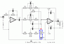
What is the significance or advantage of incorporating this resistor/capacitor in series in the following 3 band Baxandall circuit? I've also seen similar circuits, but without these two components! The values in this particular circuit are;
R10=270 ohm
C8=1.2nF
R10=270 ohm
C8=1.2nF
Attachments
Last edited:
Hi, i've never seen it before either ! Looks like an attempt to suppress oscillation etc @ around 490kHz. Maybe they used OPA's that wouldn't work properly without it ?
Thanks Zero-D,
I've actually seen this in a few 3 band Baxandall circuits, but never really understood what it was supposed to be doing! The op-amp in this circuit is NE5532!
I've actually seen this in a few 3 band Baxandall circuits, but never really understood what it was supposed to be doing! The op-amp in this circuit is NE5532!
Last edited:
I wouldn't have thought that an NE5532 would need it, but i guess they must have in those cases ! If it works, it works i suppose 😉
I'm curious to know as to what it actually does in the circuit & to know if there are any obvious performance improvements by including these 2 components!
Apart from what i said in Post #2 it could be RF etc interference suppression ! I would have thought rolling off the HF with cap across the OPA might suffice.
Probably suppressing oscillation. At frequencies where the opamp works fine the CR network does nothing, as the chip input is a virtual ground. At higher frequencies it will reduce open loop gain, thus reducing loop gain too.
Many opamps are unity gain stable.
However, many of these same opamps are not stable for gains <<1, which is the case with the Baxandall at high cut wrt gain.
The network you see raises the loop gain at HF so that the circuit remains stable. The resistor in series with the cap simply inserts a zero so that the HF loop gain limits - otherwise you would get other problems.
Last edited:
Just thinking.....am I correct in assuming that the HF gain would never go down to unity gain or for the the matter < than unity by the sheer nature of the "tone" circuit, hence would always have some gain?
I' ve built a few of these with & without & this in the circuit, but never observed any oscillation or any notisable effects even when all the controls completely turned down!
I' ve built a few of these with & without & this in the circuit, but never observed any oscillation or any notisable effects even when all the controls completely turned down!
- Status
- Not open for further replies.
- Home
- Source & Line
- Analog Line Level
- RC Chain in a 3 Band Baxandall EQ Circuit?