Summary: Lots of amps produce error that can be dominated by PS ripple, including some forum favorites.
PS ripple can couple into the signal path through various paths. Some paths are capacitive (worse at HF) and some, like Early effect, are not a function of frequency.
You might think that if ingress is worse at HF than LF, then we only need to check PSRR at the treble end of the spectrum. This turns out not to be the case, since PS ripple amplitude is probably larger at LF. Let's assume a linear power supply where the rails are fed from large reservoir filter caps. And let's assume some upper bound on the amount of current flowing into or out of those caps. That puts an upper bound on the rails' slew rate, which in turn limits the amplitude of rail ripple to lower levels at HF than at LF.
If you model PS ripple as a signal that increases in level at LF -- and of course it'll have a substantial 120Hz component-- you'll find that many amps have more PS ingress at LF than at HF.
I've been simulating PSRR by modeling the rails as an AC voltage source with a large DC offset, and an AC amplitude of 333/FREQ so it's largest at LF and small at HF. (That figure assumes a 10000uF filter cap, and 20A peak charge or discharge current, which should be nearly a worst case.)
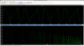
Lots of amps perform worse at LF. For example the spectrum below is the Wolverine. Its B+ rail is driven with a 40Hz ripple, amplitude 333/40 or about 8V. Its B- rail is driven with a 60Hz ripple, amplitude 333/60 or about 5.5V. There's no input signal. The output has an amplitude near 1mV peak to peak, all noise. That's not terrible, but it's a larger error than we expect from distortion, given this amp's near-ppm distortion performance. If we're driving program material at nearly full amplitude, 100V peak to peak, the 1mV error due to PS ingress is 100dB below the signal and still 20dB above the distortion floor.
Is this a real problem? Maybe not, but it's worth paying attention to, given that PS ingress can be worse than distortion. At least given assumptions that are somewhere between conservative and wildly pessimistic. :^)
(Left as an exercise: what is the actual spectrum of ripple, and is there a better way to model it in simulation?)
PS ripple can couple into the signal path through various paths. Some paths are capacitive (worse at HF) and some, like Early effect, are not a function of frequency.
You might think that if ingress is worse at HF than LF, then we only need to check PSRR at the treble end of the spectrum. This turns out not to be the case, since PS ripple amplitude is probably larger at LF. Let's assume a linear power supply where the rails are fed from large reservoir filter caps. And let's assume some upper bound on the amount of current flowing into or out of those caps. That puts an upper bound on the rails' slew rate, which in turn limits the amplitude of rail ripple to lower levels at HF than at LF.
If you model PS ripple as a signal that increases in level at LF -- and of course it'll have a substantial 120Hz component-- you'll find that many amps have more PS ingress at LF than at HF.
I've been simulating PSRR by modeling the rails as an AC voltage source with a large DC offset, and an AC amplitude of 333/FREQ so it's largest at LF and small at HF. (That figure assumes a 10000uF filter cap, and 20A peak charge or discharge current, which should be nearly a worst case.)
Lots of amps perform worse at LF. For example the spectrum below is the Wolverine. Its B+ rail is driven with a 40Hz ripple, amplitude 333/40 or about 8V. Its B- rail is driven with a 60Hz ripple, amplitude 333/60 or about 5.5V. There's no input signal. The output has an amplitude near 1mV peak to peak, all noise. That's not terrible, but it's a larger error than we expect from distortion, given this amp's near-ppm distortion performance. If we're driving program material at nearly full amplitude, 100V peak to peak, the 1mV error due to PS ingress is 100dB below the signal and still 20dB above the distortion floor.
Is this a real problem? Maybe not, but it's worth paying attention to, given that PS ingress can be worse than distortion. At least given assumptions that are somewhere between conservative and wildly pessimistic. :^)
(Left as an exercise: what is the actual spectrum of ripple, and is there a better way to model it in simulation?)
Attachments

Lots of amps produce error that can be dominated by PS ripple ...
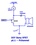
Here is one that doesn't. Nelson Pass's "DIY Sony VFET pt.1" (link to Forum thread) --Simplified schematic attached below.
This amp operates in Class A. Its supply current is perfectly constant and independent of the load current. The same supply current flows whether the amplifier is producing zero output, or 100% max possible output. The output waveform does not modulate the supply current.
And oh by the way, the same is true of the current flowing in the amplifier ground ("wire A" in the diagram). It too is constant and independent of the output waveform. Kirchoff's Curent Law is a wonderful thing.
Nelson specified an SMPS "brick" to provide the +36V supply, with a C-L-C postfilter to reduce any high frequency switching artifacts that it might spray onto the +36V buss.
_
Attachments
That is likely more ripple than the ripple-eaters can remove.jpc2001 said:For example the spectrum below is the Wolverine. Its B+ rail is driven with a 40Hz ripple, amplitude 333/40 or about 8V. Its B- rail is driven with a 60Hz ripple, amplitude 333/60 or about 5.5V.
I notice the trend is to use unregulated supplies based on the assumption that a high-feedback amplifier is a regulator. This is motivated by cost-performance.
Back when feedback was not very high, voltage regulation mattered. I use regulated supplies for all but the last stage. In addition to not having ripple, the regulated supply enables the amplifier's output to swing closer to the lower-voltage unregulated supply, improving efficiency. Of course, an additional power supply is needed.
Ed
We don't need an exotic class A amplifier to fix this, it's possible to reduce PS ingress as far as you like in a conventional class AB design.
"Ripple eaters" are most effective at HF. That's true for both passive R-C filters and active cap multipliers. Since ripple is loudest at LF, the ripple eaters aren't ideal. I'm thinking a better technique is to cascode IPS and VAS transistors to suppress injection at all frequencies. Of course you have to reference each cascode to the local rail, not ground, for it to be effective.
The main thing is to simulate with HF and LF rail noise, on both rails, and verify high PSRR over a broad spectrum. Accomplishing it is open to creativity. 🙂
Old amplifiers did that too because high-voltage transistors did not exist.jpc2001 said:I'm thinking a better technique is to cascode IPS and VAS transistors to suppress injection at all frequencies.
My point was that the techniques to get superb PSRR are all well-known, have been done, and then fell into disuse because cranking up the feedback was cheaper.
Ed
It is basically a non-issue with regular, conventionally designed amplifiers: they have an built-in PSRR rejection.
Exotic or some class A amplifiers are less immune, but that's purely your choice and if you go that way, you must be prepared to some inconvenience (perfectly manageable, but is it required?)
Exotic or some class A amplifiers are less immune, but that's purely your choice and if you go that way, you must be prepared to some inconvenience (perfectly manageable, but is it required?)
The original post assumed a filter cap with no parasitics, but the picture changes if you look at ESR.
A large electrolytic might have 25 mOhm of ESR. For a 15,000uF cap, its capacitive impedance roughly equals its ESR somewhere around 400 Hz, with ESR dominating at higher frequencies.
So it's not really correct to model ripple falling away, inverse with frequency through the whole audio band. Beyond 400Hz it stops falling. So we still should consider, model, and minimize HF ingress mechanisms (bjt Cob and the like.)
Not exactly the point of the topic, but a very good solution to the issue 🙂
This single rail power supply is an improvement over R21 power supply add-on module. It has an active rectifier, RF filter and super-regulator on a single compact PCB (120 x 70 mm). Performance is comparable to R21, except for the PSRR at high frequency, where this new supply maintains > 60 dB PSRR far into MHz range. It doesn’t have, for now, negative voltage counterpart.
It works, as is without any changes, from 10 to 60 V output voltage for a version without RF filter. Max. output voltage for a version with RF filter is 50V. Output current is up to 10 A (20 A short...
It works, as is without any changes, from 10 to 60 V output voltage for a version without RF filter. Max. output voltage for a version with RF filter is 50V. Output current is up to 10 A (20 A short...
- tombo56
- Replies: 358
- Forum: Power Supplies
- Home
- Amplifiers
- Solid State
- "Railing" about PSRR :-)