Hello everybody! I was given as a gift an old stationary radio made in Romania. Aesthetic it looks good for its age. I switched it on but it was heard only a noise and very weak sound. Both potentiometers for tone and volume were broken. There is a liniar design and I used one of those that I have for testing the radio. Generally it tunes into stations on LW is weak, decalibrated from the scale, on MW is somehow good, on 49M 1-2 stations and on the other two SW bands just some noise (because I didn't have an external antenna). On old OIRT FM I can tune with good sound a station which broadcasts 3h/day on 69,53 MHz. I made also a test with an FM converter (CCIR->OIRT) and also the sound was good.
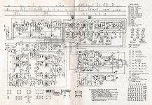
Because the radio has a noise on the audio amplifier, I touched some components to see from where it could come. I saw that a transistor T403 was running very hot so I checked the power supply.. Instead of 15V it delivered 21V. I checked the medium power transistor AD155 and the E-C region was in shortcircuit. I used for negative an LM335 and adjusted to 14,9V. Now the driver transistor isn't running hot, but the noise persists. I desoldered any other links towards radio RF board and I let just the audio amplifier. At 0 volume it doesn't make any sound, but while I increase the volume even without any signal it makes a noise as "something was not soldered to the ground". If I touch the chassis, the noise vanishes. I changed for the moment C406 (10uF) and C408 (100uF). The same problem. The amplifier plays well and powerfull, the final transistors don't run hot. I tried to disconnect C405 (100nF) and as long as the noise vanished even in the absence of a potentiometer. I put the potentiometer cursor there and even at maximum (but with lower amplification) there was no noise. What it could be? A problem regarding the area of T401? Maybe the transistor is having too much hFE (beta) and it can pick-up easily any noise? Or because of its high impedance it could pick-up noise easier?
Another question regarding the ground is why some designs have GND soldered at "+" at the power supply, but the audio amplifier is having the ground at "-", while the RF part is linked through the RF coils to GND (+) because of NPN transistors. It couldn't been possible linking the emitors through their resistors at "-" for having the entire device the same rail polarity?