Apologies if I have missed a previously posted answer. However...
When extending amplifier performance to higher power the F5 is typically chosen as the starting point; F5, F5 Turbo V1, V2, V3...
Assuming that one will need to use multiple matched devices to spread thermal loading and that one wants near identical performance from all devices to provide best cancellation of `errors', wouldn't it be a lot easier to find near identical performance using a single device type rather than try to match complementary pairs?
Wouldn't the F6 be a better starting place?
Is the answer as simple as the problems introduced by trying to get well matched complementary pairs are outweighed by the errors introduced by adding a transformer?
Hoping for illumination,
matter of approach
first, who sez that everyone's goal is to have identically functioning parts in upper and lower half of an amp?
that, same as most other things, need to be informed choice
first, who sez that everyone's goal is to have identically functioning parts in upper and lower half of an amp?
that, same as most other things, need to be informed choice
How much higher performance?
What types of speakers are the target?
Need higher voltage rails, higher bias current, or both?
Wise Zen Mod is correct in that deliberate mismatch (in small amounts) can be fun to listen to.
What types of speakers are the target?
Need higher voltage rails, higher bias current, or both?
Wise Zen Mod is correct in that deliberate mismatch (in small amounts) can be fun to listen to.
Thanks for your thoughts.
I appreciate that the desired `sound' (phase and magnitude of additional harmonics), is at some point of greater importance than further reduction of THD. I also recall that Picodumbs chose dissimilar devices in his F6 to get a sound he wanted.
My starting assumption was that push-pull amplifiers with multiple output pairs would mean that the greater number of devices might result in a greater number of harmonics and a `messier' spectrum. So I was wondering wether perhaps the F6 architecture with multiple well-matched devices of a single species might be a better starting point when you want to `deliberately and carefully unmatch' top to bottom, in order to get the sound you want.
Then again, if all the n-types and all the p-types are well matched to each other, then maybe you can treat them all as a single pair and this isn't a problem.
Equally perhaps the transformer has a greater influence.
@TA Magenpans, so probably a two pairs of outputs per channel, higher bias current but probably no more volts. Sounds like F5 Turbo V1 or V2
Maybe an F6 derivative with a diamond buffer could drive two large devices which obviates the need for multiple output pairs
large devices - if you think of IXYS pucks - that needs special care taken with their biasing mechanism, Berserking xconductance is very serious thing
at least I'm Chicken - to even think having passive biasing with those
at least I'm Chicken - to even think having passive biasing with those
I will be listening to an F6 with a Diamond buffer later today. Output devices with be from my stash of FQH44N10 – high transconductance and high power dissipation. Speakers are Vandersteen 3A Signature. The new boards incorporate dissimilar Source resistor networks to tweak asymmetry how one likes.
Short of the big IXYS pucks, the FQH44N10 are about the best that can be found in single devices with reasonable input capacitance, pretty easy to drive & bias. I'm keeping an eye on other devices as well. The IRFP048 performed very well in the 'standard' F6 configuration.
Short of the big IXYS pucks, the FQH44N10 are about the best that can be found in single devices with reasonable input capacitance, pretty easy to drive & bias. I'm keeping an eye on other devices as well. The IRFP048 performed very well in the 'standard' F6 configuration.

Generally speaking, matching devices is important when you are paralleling them so as to
have similar bias current through each. Even that can be adjusted by trimming any Source
resistors. Similarly, you can trim Source resistors on the positive and negative sides of an
output stage so as to null or otherwise have some control over harmonic content.
You can play with this stuff all day long.....
So build and then iterate choices of resistors to get all bias currents very close just using a DVM to measure across the source resistor?
I assume you would need a signal generator and scope to play with harmonic content..?
WRT F6 I was thinking about 2Picodumbs recommendations for TO-247 IRFP250N and IXTH64N10L2 and operate at ~50W.
I assume you would need a signal generator and scope to play with harmonic content..?
WRT F6 I was thinking about 2Picodumbs recommendations for TO-247 IRFP250N and IXTH64N10L2 and operate at ~50W.
F5 with 32v power supplies is probably your best bet for Magnapans.
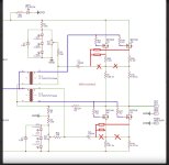
I do have a questions for anyone who may know the answer... ☝️... Does this look like it will work? Basically a F6 but with paralleled output devices as well as a couple of other tweaks. Maybe with some higher voltage rails... Say 30vdc.

I do have a questions for anyone who may know the answer... ☝️... Does this look like it will work? Basically a F6 but with paralleled output devices as well as a couple of other tweaks. Maybe with some higher voltage rails... Say 30vdc.
the Magnepans being low impedance like lower ps voltage and high bias current.F5 with 32v power supplies is probably your best bet for Magnapans.
As for paralleling the devices I think you will want something like in the below attachement.
Attachments
How much can you raise the power supply voltage before you smoke the input Jfets? Would it make sense to create a seperate supply for the outputs? Also, how much paralleled input capacitance can the driver stage handle before it gets to be a problem? I'm watching TA's thread on the F6 Revisited.
BeardyWan, Yes, for sure the Magnepans are going to want a pretty stout amplifier. The F6, although a nice little amp, is not going to offer much control of the magnepans. It will get loud but you will hear the amp trying. I had a pair of Magnepans and tried the F6 with them.
The F5 turbo V2 would probably be a decent choice. Either that or the BA-3. The Ba3 has an extra gain stage on the front end which is nice but less outputs.
Donaldspace, 32v seems to be the safe limit for j74/k170's even though they are rated at less. 43v according to Mr. Pass is when they break down. You could run the front end on a separate supply but cascoding sounds easier.
F6: Cool, that trace was the part that I was wondering about. Back to the drawing board
The F5 turbo V2 would probably be a decent choice. Either that or the BA-3. The Ba3 has an extra gain stage on the front end which is nice but less outputs.
Donaldspace, 32v seems to be the safe limit for j74/k170's even though they are rated at less. 43v according to Mr. Pass is when they break down. You could run the front end on a separate supply but cascoding sounds easier.
the Magnepans being low impedance like lower ps voltage and high bias current.
As for paralleling the devices I think you will want something like in the below attachement.
F6: Cool, that trace was the part that I was wondering about. Back to the drawing board
There is a difference between smoking the devices and shortening their lifetime. Papa Nelson is our King, we are his people. He has many spare parts to choose from if a couple go bad from excess voltage.
My personal limit for the 2SJ74 would be 26V, one volt more than the maximum rated value. One needs to bear in mind that the linear characteristics of the device depend on working conditions remaining within the maximum Vgds rating. The 2SK170 is rated for 40V and is the more robust of the two.
My personal limit for the 2SJ74 would be 26V, one volt more than the maximum rated value. One needs to bear in mind that the linear characteristics of the device depend on working conditions remaining within the maximum Vgds rating. The 2SK170 is rated for 40V and is the more robust of the two.
Well, the BA-3 and F5 Turbo have been out for quite a while... A lot of them with the suggested 32v rails. Are there any reports of the JFETs having issues? I would say cascode them (because why not) but I do not believe there is an easy-to-buy board out there with cascoded JFETs for the F5. For someone who wants to just take the paint-by-color approach...
Yes, and the F5 Turbo uses 1k resistors above and below the JFets plus source resistors in-between. At 8mA current, the 1k resistors will drop 8V, placing the 2sJ74 in safe territory.
Mine has run at 32 volts for years now. Toshiba jfets.Well, the BA-3 and F5 Turbo have been out for quite a while... A lot of them with the suggested 32v rails. Are there any reports of the JFETs having issues? I would say cascode them (because why not) but I do not believe there is an easy-to-buy board out there with cascoded JFETs for the F5. For someone who wants to just take the paint-by-color approach...
Bubba
So I have to revise my mentioning that Pass stated 32v as the max. I loosely remembered that figure from the BA-3 article. Referring back to it, my information was wrong.
"The supply voltage is only critical with respect to the voltage rating of the input JFETs, which are nominally 25 volts. In actual testing, they break down around 40 volts. I wouldn't worry about running them as high as 30V."
"Coming off the Drain of Q1 is the loading network of R6, C1 and P1".....
"R6 clearly sets the AC load for Q1, but the DC requirements to bias up Mosfet Q3 are higher than that, so P1 in parallel with C1 provides a higher resistance value below about 0.5 Hz, and gives the approximately 3 volt DC drop required to bias the Mosfets."
Okay so the JFETs in the BA-3 with the 32v power supply should see around 29vdc. I suppose that is the more comfortable max. I never considered the fact that the current the JFETs draw had a significant effect on dropping the voltage. But it makes sense you need that voltage drop to drive the next stage... duh.
Maybe I will try running JFETs at a higher voltage to see what goes boom.
- Home
- Amplifiers
- Pass Labs
- Quick question about F6 vs F5