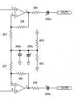
I'm trying to pick some better capacitor values for the part of a circuit shown below (dont ask me what it's for, you'll just laugh). Before this final amplifying stage there's a bunch of transistors summing signals from some DACs and a low pass filter (22nF to ground). The signals are 0-5v with 2.5v offset.
When I calculate the cutoff frequencies ot the bias filter and the output AC coupling (assuming I'll connect the the outputs to the line level input of a Hi-Fi amplifier) I get: Output = ~0.03Hz, Bias = ~7Hz.
I've read somewhere that the bias cutoff should be 1/10 of the amp cutoff to minimize the noise from the bias circuit. Is that right?
The design on the picture is doing the opposite, and I'd like to correct that if it's possible (or even necessary?). I'd like to use a pair of 10uF MKP4s for the output AC coupling. 100uF seems a bit overkill. But can I use a smaller value? How "high" can you make the cutoff frequency before it starts getting audible?
If I go with 10uF caps on the output, I'll have to use 22000uF caps on the bias instead of the 100uF to get 1/10 of the output cutoff (unless I'm doing all of these calculations wrong... there's a good chance of that). I guess I can do that by paralleling 10x 2200uF. But will it have some bad side effects (22000uF sounds huge to me)? Is it even worth the trouble?
Attachments
It depends on your loudspeakers. If they only go down to 40Hz then there seems no point in sending 0.03Hz to the power amp; it may even be harmful to sound, as any subsonics from your sources will keep the power amp busy.How "high" can you make the cutoff frequency before it starts getting audible?
Good point 🙂
Mine only goes down to 44Hz. So it would be safe to cut the output somewhere around that?
Mine only goes down to 44Hz. So it would be safe to cut the output somewhere around that?
No, go a bit lower - maybe 10-15Hz. This reduces phase shift. You can always push the bias decoupling down a bit more, but no need to take it too far.
Your bias circuit looks ok.
The 470r seems a bit low, I use 10k's in my mixer circuit with 10 op amps on the bias line.
If you want to lose the 2v5 bias put a capacitor on the input to the op-amps, this will kill any DC.
The 470r seems a bit low, I use 10k's in my mixer circuit with 10 op amps on the bias line.
If you want to lose the 2v5 bias put a capacitor on the input to the op-amps, this will kill any DC.
Your bias circuit looks ok.
It's not my design, but thanks anyway 😉
The 470r seems a bit low, I use 10k's in my mixer circuit with 10 op amps on the bias line.
I've been told that they need to be as small as possible (within reason) to keep the feedback resistors out of the equation. And the whole circuit only has a single 5v rail to work with, so the current draw is quite low.
If you want to lose the 2v5 bias put a capacitor on the input to the op-amps, this will kill any DC.
That would be the optimal solution. But at the moment the I'm limited by the 5v supply.
I would increase the 470, too. This will reduce the DC and subsonic gain, so the circuit will cope better if the input bias is not exactly 2.5V.
Ahh yes, I think I had my info on AC and DC coupling mixed.
The resistors only needs to be low if the amp is DC coupled, right?
I'll replace them with 10K 😀
The resistors only needs to be low if the amp is DC coupled, right?
I'll replace them with 10K 😀
- Status
- Not open for further replies.
- Home
- Source & Line
- Analog Line Level
- Questions about AC coupling and opamp biasing