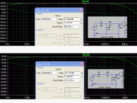
I was analyzing some amp circuits, see that the most, use of filter resistor before the resistor that sets the input impedance. I think it is harmful this causes a voltage divider and also will increase the input impedance.
I would like to know opinions.
Thanks
I would like to know opinions.
Thanks
Attachments
if there is no series resistor the capacitor across R25 will not work to reduce the rf frequencies. The value is normally 1/10 of the input resistor. You can leave it out if you wish. You should put a large resistor at least 10x the value of r25 in front of the input capacitor to ground. This will allow the input capacitor to discharge. You can leave this out as well if you do connect disconnect the input a lot from the source.
if there is no series resistor the capacitor across R25 will not work to reduce the rf frequencies. The value is normally 1/10 of the input resistor. You can leave it out if you wish.
The filter makes cut in two circuits. The response of this circuit is much higher without the RC filter, the voltage divider formed (first simulation) changes the frequency of cutting. But in first simulation the tendency is cancel R25, this would be his point?
Thanks for the tip. Did a fast simulation (DC), and without this resitor discharge have the DC offset of amp in input, but it is harmful?You should put a large resistor at least 10x the value of r25 in front of the input capacitor to ground. This will allow the input capacitor to discharge. You can leave this out as well if you do connect disconnect the input a lot from the source.
Thanks
I was analyzing some amp circuits, see that the most, use of filter resistor before the resistor that sets the input impedance. I think it is harmful this causes a voltage divider and also will increase the input impedance.
I would like to know opinions.
Thanks
Hi Rafael,
It's good that you are looking at them, at least.
The fact that most of them are made that way should tell you something about whether or not it's bad, or good. (And increasing the input impedance is typically "a good thing".) In commercial circuits, you might occasionally see something that was designed badly. But, most of the time, they have done a reasonably-good job of not doing anything that's actually bad.
The series capacitor followed by a resistor to ground is a high-pass filter. It is used mostly to keep out any DC offset from a previous stage or source. Its "cutoff" (or -3dB, i.e. half power) frequency, in this application, should be set well below the audio frequency range. f(-3db) = 1/(2 Pi R C)
Yes, DC offsets can be harmful. If they are large, they can damage or destroy speakers, and can also cause other problems. If they are not that large, they can cause the speaker driver to be mechanically un-centered, which might affect the speaker's performance.
A series resistor followed by a capacitor to ground is a low-pass filter, and is usually scaled so that it only attenuates radio frequency signals that are far above the audio range.
RF is bad to have in audio circuits, because the semiconductor junctions rectify it into DC (possibly changing bias setpoints and/or creating DC offsets) and/or demodulate it into unwanted "noise".
Those two types of filters are standard good design features, for the inputs of audio amplifiers.
Also, the RF filter's capacitor needs to be as close as possible to the input pin of the amplifier, since RF wavelengths can be extremely short and any significant length of wire or PCB trace after the cap to ground could act as an antenna and let in RF after the filter. So the high-pass filter has to be upstream from the low-pass filter. But it doesn't matter, because the high-pass's capacitor should look almost like a short circuit (i.e. like a piece of wire or PCB trace) to the audio signal, anyway.
Cheers,
Tom
Last edited:
I prefer the series resistor first and the grounding resistor second and in parallel with the RF filter capacitor.
This does three things.
1.) the attenuation of the two Rs exactly cancels out the +1 in the gain formula for a non-inverting amplifier. Gain of 1+Ru/Rl around the amp becomes gain of Ru/Rl from input to output.
2.) the series R first increases the input impedance slightly without any downside.
3.) the RF filter cap provides a low source impedance at HF. This cap should be very close to the input pin of the amplifier.
I also put a low value (~47pF) ceramic across the RCA input socket for exactly the reason that Gootee stated. Kill external interference before it does any damage.
The DC blocking cap needs a grounding Mohm resistor. It too can be mounted here.
- Status
- Not open for further replies.
