Hi guys, first post here and straight to the business if you don't mind.
I have had this little project going on for a while, but now it seems there's not much left to do. Still, I am wondering if any of these following circuits could be fine tuned a little further?
First picture, top row is the input circuit straight after the DAC, before the input selector. I couldn't find much specs for the DAC (MN35511AL), so I don't even know if this is I/V conversion followed by filter/buffer...or maybe MFB low pass filter followed by Sallen-Key, or then something else altogether.
I tried to calculate some basic filter values, but getting results like low pass fc around 5kHz doesn't seem to be even close to the usual values (low pass around 60-100kHz?). So obviously I can't get this right, especially not even knowing what to calculate. Any tips and/or magic formulas?
The lower part of the schematic is simple enough, a basic buffer between the input selector and the vol/tone circuits. Maybe better save that latter part for later study and start here though.
I can tell what I've done here so far if anyone is interested, all suggestions are welcome though.
Attachments
subterfuge said:Hi guys, first post here and straight to the business if you don't mind.
I have had this little project going on for a while, but now it seems there's not much left to do. Still, I am wondering if any of these following circuits could be fine tuned a little further?
First picture, top row is the input circuit straight after the DAC, before the input selector. I couldn't find much specs for the DAC (MN35511AL), so I don't even know if this is I/V conversion followed by filter/buffer...or maybe MFB low pass filter followed by Sallen-Key, or then something else altogether.
I tried to calculate some basic filter values, but getting results like low pass fc around 5kHz doesn't seem to be even close to the usual values (low pass around 60-100kHz?). So obviously I can't get this right, especially not even knowing what to calculate. Any tips and/or magic formulas?
The lower part of the schematic is simple enough, a basic buffer between the input selector and the vol/tone circuits. Maybe better save that latter part for later study and start here though.
I can tell what I've done here so far if anyone is interested, all suggestions are welcome though.
The output stage appears to be a “simplified summing” low pass filter after a balanced V out DAC. The fully balanced V out analog stage can be substituted here, with a proper bias (if DAC permits it) to omit the coupling capacitors. This should be followed by a second stage - balanced to single ended OP amp.
The bottom part is a simple buffer to provide constant low output impedance - a proper drive for a volume pot.
Hope this helps,
Regards,
Boky
Re: Re: Questins about the CRX-E150 circuits
Thanks Boky, every little detail helps me further.
Possible substitutions are a problem though. I'm OK fine tuning the part values, replacing or removing anything. But since this set is pretty tight box, there's not much room to add anything extra inside.
You mentioned a fully balanced analog stage, followed by a balanced to single-end stage. Using just one op-amp per channel would not be enough for this, I'd think? Especially if there would have to be some kind of low pass filter after these stages?
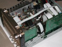
How to bias DAC I'm not familiar at all, have to study more. Here's a schematic of what has happened with this stage so far. And just to give a peek to my idea of tweaking fun, the box itself.
Thanks Boky, every little detail helps me further.
Extreme_Boky said:
The output stage appears to be a “simplified summing” low pass filter after a balanced V out DAC. The fully balanced V out analog stage can be substituted here, with a proper bias (if DAC permits it) to omit the coupling capacitors. This should be followed by a second stage - balanced to single ended OP amp.
Possible substitutions are a problem though. I'm OK fine tuning the part values, replacing or removing anything. But since this set is pretty tight box, there's not much room to add anything extra inside.
You mentioned a fully balanced analog stage, followed by a balanced to single-end stage. Using just one op-amp per channel would not be enough for this, I'd think? Especially if there would have to be some kind of low pass filter after these stages?
How to bias DAC I'm not familiar at all, have to study more. Here's a schematic of what has happened with this stage so far. And just to give a peek to my idea of tweaking fun, the box itself.
Attachments
Ah, sorry, only one image came up. Anyway, here are the mod details for this stage:
removed C328 (jumper)
removed both muting transistors
removed R366 (jumper)
I also considered changing R340 into 47-100R. The LC78211 analog switch on resistance is 150R.
Replaced electrolytics
C314/C316 with 2.2/50 MMK
C332/C329 with 4.7/50 MMK
C336/C335 with 10/63 MMK
I replaced the original NJM2068 op-amps with OP275s on the first filter stage and with OPA2134s in the buffer before VOL.
Missing from the schematic; each output line from the DAC (before this output stage) has a 47K series resistor. The MN35511AL is a DD type DAC with 8 times oversampling digital filter. I haven't found any data sheets for that one and the service manual that I have for the crx-150 doesn't give much details either.
Attachments
You could try AD826 straight after a DAC, followed by OP275 working as a buffer. The coupling caps can be Black Gate type C 4.7uF. This should give you very good results.
DAC in question is probably MASH type - Panasonic. I couldn't find the datasheet either... Being MASH type, it requires pretty steep brick-wall analog filter, so feeding the analog signal straight of the DAC output is not an option... unless you’re prepared to risk the tweeters...
Regards,
Boky
DAC in question is probably MASH type - Panasonic. I couldn't find the datasheet either... Being MASH type, it requires pretty steep brick-wall analog filter, so feeding the analog signal straight of the DAC output is not an option... unless you’re prepared to risk the tweeters...
Regards,
Boky
figuring the filters required
Sorry about my double post above, I chose a wrong shortcut from the history.
"You could try AD826 straight after a DAC, followed by OP275 working as a buffer. The coupling caps can be Black Gate type C 4.7uF. This should give you very good results."
Thanks again for your replies Boky, I appreciate your input.
So you would recommend AD826 followed by OP275? The AD826 certainly could be one nice option, many people seem to like it. My first tries were just OP275s everywhere, which was not bad sounding either. But then changing the 1st op-amps after the DAC into OPA2134 didn't feel right. So I swapped them and OP275s around. That was better and got kinda left that way so far.
Black Gates? Removing some electrolytic caps altogether, and changing most of the rest in the signal path into Evox MMK metallised polyester already made really noticeable and positive changes. There are still couple of electrolytes in the pre-amp section, maybe I'll swap those to better ones later.
While trying to figure out the DAC thing further, I noticed in the block diagram one detail that I had somehow totally ignored before. After the DD type DAC, there are actually two PEM blocks (one per channel/output pair). The output pins also read "PEM output terminal 1C" etc. PEM like Pulse Edge Modulation, the nice little D/A conversion method developed by the JVC company back in the day, perhaps?
One example of a D/A converter with similar outputs is MN35503, although that one also has something called VANS noise shaping driving the PEM blocks. Amongst all the other stuff, the MN35511AL has digital de-emphasis, 8X oversampling, digital filter, DAC and then PEM modules before the outputs.
DAC in question has differential Vout. I suggest you do the search on this forum and find the filter/buffer that can do the job better.
AD826 is a very nice OP amp. OPA2134 should be avoided in audio (my opinion) – it is frequency limited, slow and incredibly warm-wobbly. OP275 is also very nice, but shut-in compared to AD826. LM4562 is great, with its own lush and detailed characteristics.
Cheers,
Boky
AD826 is a very nice OP amp. OPA2134 should be avoided in audio (my opinion) – it is frequency limited, slow and incredibly warm-wobbly. OP275 is also very nice, but shut-in compared to AD826. LM4562 is great, with its own lush and detailed characteristics.
Cheers,
Boky
Extreme_Boky said:DAC in question has differential Vout. I suggest you do the search on this forum and find the filter/buffer that can do the job better.
Thanks again, Boky, I appreciate your input.
Yup, searched and read I have, for years on this forum and some others too. I'm still in the middle of Walt Jungs Op Amp Applications Handbook, amongst other interesting items.
The reason for me initially asking some "magic" formulas was to get insight into how I could calculate some of these circuits myself...but I quess without the real knowledge of how to do that, no loose calculations wouldn't necessarily help much. Might just end up re-inventing the wheel once again, and for what?
😉
- Status
- Not open for further replies.
- Home
- Source & Line
- Digital Source
- Questins about the CRX-E150 circuits