I try understanding how BJT cascoded over the JFET work ( the last fig./5.7 of the following link.)
ESP Amplifier Basics - How Audio Amps Work (Part 5)
1) Since BJT works as common base, current sunk from the emitter causes the transistor to conduct. So, the hfe of BJT doesn't matter -- either its hfe is low as 50 or > 300. Is that correct?
2) How to fix the Vds of Jfet (e.g. at 3V for J310) to let the jfet operate in its triode region?
Thank you in advance.
Cheers
Nelson Pass has a nice short note on cascodes. There are also several good circuit text books online.
http://www.firstwatt.com/pdf/art_cas_amp.pdf
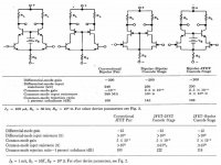
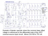
Class-A operation reduces nonlinearities due to current fluctuations through the transistor, but it does not affect nonlinearities in the transistor due to voltage changes. Cascode operation creates narrow limits in this voltage across the input transistor(FET), significantly eliminating voltage-induced distortions. In the case of JFET inputs operated in common-source mode differential pairs, the cascode bipolar transistor is in the common base mode whose emitter is connected to the drain of the JFET gain transistor. Having essentially unity current gain, extremely wide bandwidth, and no distortion, the common base device shields the gain transistor from voltage changes in the circuit.
Cascode circuits also allow low-noise or high-gain transistors with low break-down voltages to be used in high wattage circuits. The popular 2SJ109 PJFET has a break-down of just 30V.
http://www.firstwatt.com/pdf/art_cas_amp.pdf
Class-A operation reduces nonlinearities due to current fluctuations through the transistor, but it does not affect nonlinearities in the transistor due to voltage changes. Cascode operation creates narrow limits in this voltage across the input transistor(FET), significantly eliminating voltage-induced distortions. In the case of JFET inputs operated in common-source mode differential pairs, the cascode bipolar transistor is in the common base mode whose emitter is connected to the drain of the JFET gain transistor. Having essentially unity current gain, extremely wide bandwidth, and no distortion, the common base device shields the gain transistor from voltage changes in the circuit.
Cascode circuits also allow low-noise or high-gain transistors with low break-down voltages to be used in high wattage circuits. The popular 2SJ109 PJFET has a break-down of just 30V.
Attachments
To fix the drain voltage of the FET at voltage X, just set the base of the bipolar transistor to about X+0.65 Volts. You can do that with a voltage divider or a regulator. LEDs are often used for this as a shunt regularor of sorts, though usually selected because they also give nice lights!
I think it is Borbely that tells us to ensure that Vds is at least two times Vp of the jFET.....................2) How to fix the Vds of Jfet (e.g. at 3V for J310) to let the jfet operate in its triode region?
..................
What is Vp of your j310?
What would be Vds if you stick to Borbely's rule.
Borbely shows a little test jig that measures Idss, Vgs @ Id and Vp by just flicking a couple of switches.
BTW,
Borbely uses jFET cascodes because he moved over to FETs in a big way during his career.
He did show BJTs as cascodes in some locations in his very earliest designs.
Attachments
Last edited:
BTW,
Borbely uses jFET cascodes because he moved over to FETs in a big way during his career.
He did show BJTs as cascodes in some locations in his very earliest designs.
Thanks for the links to the Borbely articles, Andrew.
Regards,
Andy
- Status
- Not open for further replies.