Hi. And thanks for taking the time to read this post.
Can anyone tell me where to purchase a high performance bridge rectifier for my quad 405-2 amplifier. At the moment i have replaced the power modules with 405-3's from net audio and purchased 10,000uf caps for the power supply (not fitted yet), replaced all wiring with silver plated ptfe, high quality phono outs and finally michele speaker posts.
Also are there any instructions for the dual mono power supply.
I did a google search and there are descriptions of caps but not how to wire them up, ie which wires go where, which terminals on the transformer are to be connected to which terminals on the bridge rectifier then the caps.
Many thanks in advance. John.
You need a bridge with a high current surge ability such as,
GBPC2504 - FAIRCHILD SEMICONDUCTOR - BRIDGE RECTIFIER, 25A, 400V | CPC
It's worth adding a snubber (0.1 uf and 1 ohm in series) across each diode in the bridge to reduce commutation noise.
Wiring is straightforward but it's hard to give specifics without seeing it all.
GBPC2504 - FAIRCHILD SEMICONDUCTOR - BRIDGE RECTIFIER, 25A, 400V | CPC
It's worth adding a snubber (0.1 uf and 1 ohm in series) across each diode in the bridge to reduce commutation noise.
Wiring is straightforward but it's hard to give specifics without seeing it all.
That one came up as out of stock but there are dozens suitable,
GBPC3504 - FAIRCHILD SEMICONDUCTOR - BRIDGE RECTIFIER, 35A, 400V | CPC
GBPC3504 - FAIRCHILD SEMICONDUCTOR - BRIDGE RECTIFIER, 35A, 400V | CPC
Hi. Thanks for the reply.
So will any rectifier do, with the smoothing capacitors some brands tend to be better thsn others.
I can see the rectifer has two connections on one side which should go the transformer, then the two on the other side should go to the capaitors. Only problem my 405-2 has a fifth wire which comes from the secondary set of windings, bypasses the rectifier and goes straight to the lower capacitor the one nearest the phono inputs and the speaker output connectors.
Many thanks. John.
Any suitably rated rectifier is OK as long as from a reputable supplier so you can be sure you are getting what is advertised.
When wiring this up you need to be very careful. The AC from the transformer will go to "opposite corners" on the bridge. It should be marked on the device.
Maybe if you could post a detailed clear picture of the transformer and wiring we could identify what goes where but it will be straightforward. The original 405 had multiple secondaries connected in parallel but all very conventional.
Attachments

Hi. Thank you for the reply.
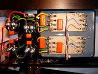
Many apologies Unfortunately I have stripped down the quad 405-2 so am unable to take a photo. However I have uploaded a photo which shows a quad 405-2 with an identical transformer to mine so some similarities can be drawn.
With my transformer the wires on the right hand side are identical to the wires on the right hand side of the uploaded photo.
On the left hand side of my amplifier’s transformer there are the same 8 terminals as the photo. The first one (highest one up) is connected to the bridge rectifier as per the photo and also is connected to the eighth terminal (lowest one down) by a piece of yellow wire.
The second and third terminals are bridged together as per the photo, but there is a green wire which also connects them both to the sixth and seventh terminal. The sixth and seventh terminals are also bridged together as per the photo.
The fourth terminal is connected to the bride rectifier as per the photo but there is a yellow wire which also connects it to the fifth terminal.
Finally as mentioned earlier the sixth and seventh terminal are connected together but there is also a wire connecting the seventh terminal to the positive terminal of the lower smoothing capacitor, the one nearest the phono input sockets and speaker output binding posts. There are only two smoothing capacitors in this case.
The uploaded photo has the dual mono supply fully installed what I am struggling to see and is not clear, is which wire goes where or how it all connects up to the bridge rectifier and capacitors.
Many thanks.
Attachments
Your description of the wiring shows it to be as in the picture I posted above.
It's just the windings connected in parallel to double the current capability. Look at my picture. It's similar to having two physically separate transformers and connecting all the wires in parallel to double it up.
So in your picture they have been separated and each set of windings (each group of four tags) powers one amplifier via its own bridge and caps.
So for each you keep the middle tags joined as shown and that is the ground (just as before). The yellow wires are the AC and go to the bridge. It doesn't matter which way round they go as long as they go to the two AC terminals on the bridge.
The caps are wired as per the originals (in my picture). They are in series so the positive of one of them does indeed go to ground (C14 in my picture).
Does that make sense ? All you are doing is separating the windings and duplicating another bridge and set of caps. If your not sure on all this then you risk damaging the amp.
Where it gets more difficult is grounding it all correctly for no hum etc. Without first hand experience of the Quad and it's wiring scheme I wouldn't like to say on that.
Hi. Thanks very much for the reply.
I am going to dash off now and pick up the rectifier and caps.
Wish me luck, it's my first time, erm first project i mean.
I am going to dash off now and pick up the rectifier and caps.
Wish me luck, it's my first time, erm first project i mean.
Just take your time with the wiring. If you are unsure then it might be a good idea to use a bulb tester for initial powering up.
Hi. Sorry to reawaken this thread from the dead.
I emailed net audio who suggested wiring the powersupply to the chassis, here is the exact reply got no idea what it means. Can anyone please explain. What does ov mean.
" Simply connect the LH speaker return to the center (0V) part of the twin caps nearest the caps for that channel and same for the right channel. Connect the same center by an individual wire to the chassis. Think of it as an H with the tall sides of the H is one channel 0V and the same for the other. The center of the H is two separate wires to the chassis. The speaker return goes to the T junction part of the H for each channel.
Best Regards
David Pritchard
0v is the zero volt line or "ground".
The big caps (the pairs) will be connected "in series" with the plus of one going to the neg of the other. That connection is the 0v line.
If in any doubt... then always measure and confirm the voltage really is zero on the point you are looking at. It would be disasterous for example to connect the speaker return to the wrong end of the cap and get a high DC voltage across the speaker.
Hi.. Many thanks for the reply.
At the moment i have the original quad power supply capacitor configuration, with the two negative speaker terminal's cables running up from the binding posts and then connecting to the chassis by being pinned under the bridge rectifier.
The two cables then become one cable and it runs to the negative terminal of the uppermost capacitor, then to the positive terminal of the lower capacitor. So this is exactly as you say with the series capacitor.
So for the dual mono power supply, should i keep the two negative speaker cables connected to the chassis (rather than letting them become one cable) and run one to the first pair of capacitors, then run the second to the second pair of capacitors, copying quad's wiring arrangement for each as mentioned above.
Hope this make some kind of sense.
Many thanks.
Its hard to say without having seen how its all related and connected up. The aim is to have the speaker returns go to a point that is both "clean" and that also will not influence the other parts of the circuit when large speaker currents flow. This is where many designs fail and the outcome is either/or hum and noise and the more subtle effect of one channel modulating the other.
If its dual mono then that implies separate PSU's for each channel. And its very hard to say. There should be a clean ground point tapped "off" that centre connection between the caps that can be used. This same point should be used as a ground for the rest of that channel too but arranged so that interaction is minimal between the speaker current and signal current.
Next problem is when you then join these points together at the chassis... and that is OK in itself. Where problems might arise is when the input grounds themselves connect together at the preamp etc because that then forms a "loop" that circulating current can flow in (the speaker current).
Without knowing how the Quad was arranged and built its not possible to just give a "connect this here and that there" answer I'm afraid.
This thread touched on all this and might help explain it,
http://www.diyaudio.com/forums/soli...-lin-topology-nfb-tappings-2.html#post1624677
Hello,
I do not have too much financial means to explore the world of hifi.
So a few tweaks will allow me to fit a technics amplifier with a mission to keep the remote control, the delay hp, hp protection, preamp, tuner and if possible home theater. I forgot the food!
The technics have a hp output A and output B hp then I'll use part A or B mode Technics and the other output fully isolated (nearly) 405 QUAD modules (import PCBs).
Experiences there I'll tell you mine.
Last edited:
Hi. Thank you for the reply.
Many apologies Unfortunately I have stripped down the quad 405-2 so am unable to take a photo. However I have uploaded a photo which shows a quad 405-2 with an identical transformer to mine so some similarities can be drawn.
With my transformer the wires on the right hand side are identical to the wires on the right hand side of the uploaded photo.
On the left hand side of my amplifier’s transformer there are the same 8 terminals as the photo. The first one (highest one up) is connected to the bridge rectifier as per the photo and also is connected to the eighth terminal (lowest one down) by a piece of yellow wire.
The second and third terminals are bridged together as per the photo, but there is a green wire which also connects them both to the sixth and seventh terminal. The sixth and seventh terminals are also bridged together as per the photo.
The fourth terminal is connected to the bride rectifier as per the photo but there is a yellow wire which also connects it to the fifth terminal.
Finally as mentioned earlier the sixth and seventh terminal are connected together but there is also a wire connecting the seventh terminal to the positive terminal of the lower smoothing capacitor, the one nearest the phono input sockets and speaker output binding posts. There are only two smoothing capacitors in this case.
The uploaded photo has the dual mono supply fully installed what I am struggling to see and is not clear, is which wire goes where or how it all connects up to the bridge rectifier and capacitors.
Many thanks.
Ummm... That photo is from my site - Quad 405-2 upgrades
The full wiring schematic for the PSU is on that page as is a complete bill of materials including Farnell part numbers for the bridges and everything else etc. - any questions, drop me a line...
Cheers
- Status
- Not open for further replies.
- Home
- Design & Build
- Parts
- quad 405-2