Hi,
I have built up new clone boards for an old non working 303 I bought recently and can only achieve 12.7 volts maximum on each board despite being able to set the regulator voltage to 67 volts as it should be.
I have checked I haven't done anything silly and cannot see anything obvious, but have duplicated the problem as it is the same on both boards!
Any suggestions?
Thanks,
Colin
Sounds like you are measuring the voltage drop across the voltage regulator via the wrong ground point,chassis ground is not the same as the power supply ground as the voltage regulator is in the ground side not the positive as in most votage regulators.Cheers.Hi,
I have built up new clone boards for an old non working 303 I bought recently and can only achieve 12.7 volts maximum on each board despite being able to set the regulator voltage to 67 volts as it should be.
I have checked I haven't done anything silly and cannot see anything obvious, but have duplicated the problem as it is the same on both boards!
Any suggestions?
Thanks,
Colin
Thanks for explaining the regulator is the ground side - I am measuring from pin 1+5 as per the Dada instructions. Cheers.
Measure between pins 1 and 8 or 9Hi,
I have built up new clone boards for an old non working 303 I bought recently and can only achieve 12.7 volts maximum on each board despite being able to set the regulator voltage to 67 volts as it should be.
I have checked I haven't done anything silly and cannot see anything obvious, but have duplicated the problem as it is the same on both boards!
Any suggestions?
Thanks,
Colin
Hi,
I have built up new clone boards for an old non working 303 I bought recently and can only achieve 12.7 volts maximum on each board despite being able to set the regulator voltage to 67 volts as it should be.
I have checked I haven't done anything silly and cannot see anything obvious, but have duplicated the problem as it is the same on both boards!
Any suggestions?
Thanks,
Colin
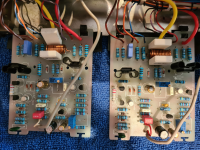
Attachments
I'm not following some of your reported measurements.
If I understanding correctly, you observe 67 VDC from pin 1 to 8, so the regulator would appear to be working. But you "only achieve 12.7 volts maximum on each board." Is this 12.7 V a DC or an AC voltage? And what are the measured voltmeter points, both "red" and "black" leads? "Maximum" is onset of distortion? Something else? Please elaborate.
Thanks.
+1 BSST
Isn't the power supply the same for both amp boards? Sounds to me like what a favorite tech-friend of mine used to call 'cockpit error'. 😉
If you're measuring from pin 1 to pin 5 of either amp board, you're actually measuring the 'positive rail to DC output' voltage -- probably not correct, but also not an indication of a power supply problem.
Regards
Last edited:
It became apparent I had the BD140's in the wrong way round so after correcting this I then couldn't get the voltage below 52V and something has fried on one of the boards creating the magic blue smoke 😢
I'm not going to get another chance to look at this for a couple of weeks now due to other commitments.
Thanks for all the comments - I need to scratch my head a bit and try and work out what has gone wrong!
Cheers,
Colin
I'm not going to get another chance to look at this for a couple of weeks now due to other commitments.
Thanks for all the comments - I need to scratch my head a bit and try and work out what has gone wrong!
Cheers,
Colin
- Home
- Amplifiers
- Solid State
- Quad 303 Clone - Only 12V on each board despite 67V after regulator board