My monster is coming alive......
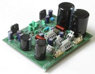
I start with AD8620 as buffer and will also test big caps vs. small caps. The little one is 1200 uF, the next is 2200 uF and the big mama is 10000 uF. All types are ELNA LP3J.
The inductor is only for the picture. The size and the need for it isn't investigated yet.
The left side is non-inverting buffer and non-inverting LM3886 and the right side is inverting buffer and inverting LM3886
Attachments
tiroth and two more people are building prototypes. I'm also going to get my working eventually.
Note also that I use Wago connectors which are unique, Noone has used those before. The effect is similar as peeling the capacitor covers off. 😎
Note also that I use Wago connectors which are unique, Noone has used those before. The effect is similar as peeling the capacitor covers off. 😎
Thanks!sonnya said:🙂 Looks very good!
How does it perform?
I don't know yet but I'll hope that tiroth will give us a report soon.
Mr Daniel has made his thumb
 already but I have some hope still left.
looking at your site there's probably few things he'd give a ( no offense peter 🙂).
you're using pcb's and it looks pretty complex. There goes the 'less is more' philosophy...
Anyway, it looks like a promising design for a (commercial?) integrated amp. Keep us informed on your progress guys!.
( no offense peter 🙂).you're using pcb's and it looks pretty complex. There goes the 'less is more' philosophy...
Anyway, it looks like a promising design for a (commercial?) integrated amp. Keep us informed on your progress guys!.
The less is more philosophy is very much possible, even for my pcb! I have made an option for it. Just check model 5 and model 6.matjans said:lyou're using pcb's and it looks pretty complex. There goes the 'less is more' philosophy..
That's one damnbloodygood looking monster.
How did you get to the name QRP ? QRP is the code for lowering power or low power in radio communications. In ham radio this is usually below 10 Watts.
Regards
Charles
P.S. I have already used Wago clamps for prototypes on Veroboard, because it gives less hassle when anything has to be disconnected in order to solder or desolder parts on the board.
www.analog.com => TNT delivery for free!stappvargen said:Hi PA!
Where did you get a hold on AD8620 in Sweden?
PS: Nice looking PCB!
Thanks!
QRP is more "Iow power" or "I'm decreasing the output power". My other amp is called QRO, 2 x 300 W.phase_accurate said:That's one damnbloodygood looking monster.
How did you get to the name QRP ? QRP is the code for lowering power or low power in radio communications. In ham radio this is usually below 10 Watts.
Regards
Charles
P.S. I have already used Wago clamps for prototypes on Veroboard, because it gives less hassle when anything has to be disconnected in order to solder or desolder parts on the board.
QRV = "I'm ready to transmit or recieve"
QSX = "Which frequency are you listening to"
For lab use Wago 224 and 215 is really really cool.
My other amp is called QRO, 2 x 300 W.
Dr OM
Didn't know that you have a QRO as well, in this case I understand your naming !
--... ...--
---- .- .-. .-.. . ... -..-. .... -... ----. --. -... --.-
It actually isn't complex unless you want it to be. I like it because it gives you a structured "playground" to try different configurations, including filters, etc. And since it has 2 channels, you can compare (as shown, with one inverting , one NI)
Amplifier
Looks good,
Per Anders, Do you have a schematic of this amplifier?
When it is somewhere on the net, please give the link.
Regards
Kurt
Looks good,
Per Anders, Do you have a schematic of this amplifier?
When it is somewhere on the net, please give the link.
Regards
Kurt
Re: Amplifier
Look at his homepage under Gainclone.
Kurt said:Looks good,
Per Anders, Do you have a schematic of this amplifier?
When it is somewhere on the net, please give the link.
Regards
Kurt
Look at his homepage under Gainclone.
The monster is alive. Seems to work very nicely so far without heatsink. Output offset 115 uV, Left channel, 10 uV!! Right channel. I haven't put through music yet but the weekend is saved 😀
The first time I tested I forgot to solder a couple of wire jumpers = some current = hot. The LM3886 didn't go
The first time I tested I forgot to solder a couple of wire jumpers = some current = hot. The LM3886 didn't go
cool, that's a nice looking PCB. it looks like it has labels, unlike my micro-PCB, which i'm noticing is having some issues. i think i'll need to make it twice as big for any real commercial use. it uses lm4780 and i think i'll make 2.2" x 2.2" version. it won't have nearly as many options though!
- Status
- Not open for further replies.
- Home
- Amplifiers
- Chip Amps
- QRP-01 the monster LM3886 Gainclone