Hi everybody,
I'm doing some tests on some cheap LDRs called LCR-0202 (they can be found on various cheap music equipments), that I want to share.
The purpose is to find a correlation between the PWM used to control them (supplied with 5V), and their resistance.
The needed material is:
- an Arduino (I'm using a Mega 2560, but every Arduino can be used, from Nano to Uno to Due, etc...);
- a DHT22 temperature and humidity sensor;
- a PCA9685 16 channel 12 bit PWM controller;
- up to 16 LCR-0202 to be tested (the limit is the number of PWM outputs of the PCA9685 and the number of analog inputs of the Arduino);
- one LED to have a visual feedback of the actual PWM;
- a 20x4 LCD screen (can be a 16x2 too, it just needs to be redrawn).
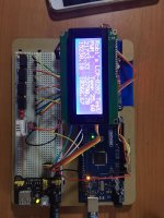
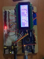
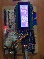
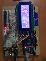
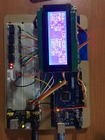
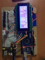
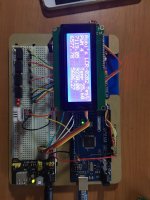
In the attached photos you'll see the values of four LCR-0202s shown on screen:
Second line shows the actual PWM command (the lower the value, the lower the current through the led, so the higher the resistance of the LDR), and the actual ambient temperature.
Third and fourth lines show the actual value in Ohms of the four LDRs.
Has anyone done some tests on those, or has direct experience?
Thanks
I'm doing some tests on some cheap LDRs called LCR-0202 (they can be found on various cheap music equipments), that I want to share.
The purpose is to find a correlation between the PWM used to control them (supplied with 5V), and their resistance.
The needed material is:
- an Arduino (I'm using a Mega 2560, but every Arduino can be used, from Nano to Uno to Due, etc...);
- a DHT22 temperature and humidity sensor;
- a PCA9685 16 channel 12 bit PWM controller;
- up to 16 LCR-0202 to be tested (the limit is the number of PWM outputs of the PCA9685 and the number of analog inputs of the Arduino);
- one LED to have a visual feedback of the actual PWM;
- a 20x4 LCD screen (can be a 16x2 too, it just needs to be redrawn).
In the attached photos you'll see the values of four LCR-0202s shown on screen:
Second line shows the actual PWM command (the lower the value, the lower the current through the led, so the higher the resistance of the LDR), and the actual ambient temperature.
Third and fourth lines show the actual value in Ohms of the four LDRs.
Has anyone done some tests on those, or has direct experience?
Thanks
Code:
#include <Wire.h>

//to manage the LCR-0202s
#include <Adafruit_PWMServoDriver.h>
Adafruit_PWMServoDriver pwm = Adafruit_PWMServoDriver();

//just to show results
#include <LiquidCrystal_I2C.h>
LiquidCrystal_I2C lcd(0x27, 20, 4);

//to read ambient temperature
#include <SimpleDHT.h>
int pinDHT22 = 2;
SimpleDHT22 dht22;
float temperature = 0;
float humidity = 0;

//just an array of 2^n
int pwm_values[] = {0, 1, 2, 4, 8, 16, 32, 64, 128, 256, 512, 1024, 2048, 4095};

//analog readings in voltage dividers
float a_read1 = 0;
float a_read2 = 0;
float a_read3 = 0;
float a_read4 = 0;

//LCR-0202 initial resistance values
float LCR1_ohm = 0;
float LCR2_ohm = 0;
float LCR3_ohm = 0;
float LCR4_ohm = 0;

//define "leak" resistors in voltage dividers
float bottomR1_ohm = 1000;
float bottomR2_ohm = 1000;
float bottomR3_ohm = 1000;
float bottomR4_ohm = 1000;

void setup() {
  //PWM startup
  pwm.begin();
  pwm.setPWMFreq(500); //to avoid wavering of the light

  //LCD startup
  lcd.init();
  lcd.backlight();
  lcd.clear();
}

void loop() {
  for (int i = 0; i < 14; i++) {
    for (int led_num = 0; led_num < 6; led_num++) {
      if (i == 0) {
        pwm.setPWM(led_num, 4096, 0);
      }
      pwm.setPWM(led_num, 0, (4095 - pwm_values[i]));
    }
    delay(2000);
    show_values(i);
  }
}

void show_values(int i) {
  lcd.clear();
  lcd.print("Robi's LCR-0202 Test");

  lcd.setCursor(0, 1);
  lcd.print("PWM ");
  lcd.print(pwm_values[i]);

  lcd.setCursor(10, 1);
  dht22.read2(pinDHT22, &temperature, &humidity, NULL);
  lcd.print("Temp ");
  lcd.print(temperature);

  lcd.setCursor(0, 2);
  a_read1 = analogRead(0);
  LCR1_ohm = ((1023 * bottomR1_ohm) / a_read1) - bottomR1_ohm;
  lcd.print(LCR1_ohm);

  lcd.setCursor(10, 2);
  a_read2 = analogRead(1);
  LCR2_ohm = ((1023 * bottomR2_ohm) / a_read2) - bottomR2_ohm;
  lcd.print(LCR2_ohm);

  lcd.setCursor(0, 3);
  a_read3 = analogRead(2);
  LCR3_ohm = ((1023 * bottomR3_ohm) / a_read3) - bottomR3_ohm;
  lcd.print(LCR3_ohm);

  lcd.setCursor(10, 3);
  a_read4 = analogRead(3);
  LCR4_ohm = ((1023 * bottomR4_ohm) / a_read4) - bottomR4_ohm;
  lcd.print(LCR4_ohm);
  }
Attachments
Last edited:
Here you can find the datasheets:
- LCR0202 http://p.globalsources.com/IMAGES/PDT/SPEC/684/K1051105684.pdf
- PCA9685 http://www.nxp.com/documents/data_sheet/PCA9685.pdf
- DHT22 https://www.sparkfun.com/datasheets/Sensors/Temperature/DHT22.pdf
- 20x4 LCD https://www.beta-estore.com/download/rk/RK-10290_410.pdf
- i2C interface https://cdn-learn.adafruit.com/downloads/pdf/i2c-spi-lcd-backpack.pdf
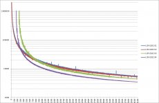
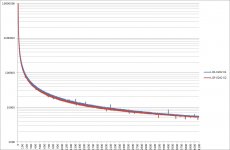
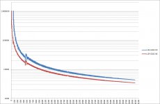
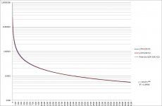
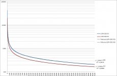
Some plots of the data I've got with yesterday's tests:
Attachments
-
 LCR-0202-33k-unbypassed-A&B&C&D.jpg77.3 KB · Views: 81
 -
 LCR-0202-33k-unbypassed-100k-leak-A&B.jpg69.2 KB · Views: 65
 -
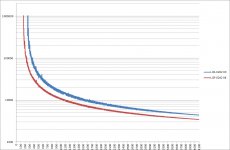 LCR-0202-33k-unbypassed-1k-leak-C&D.jpg69.9 KB · Views: 60
 -
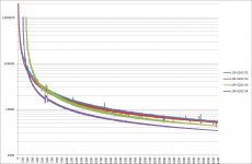 LCR-0202-33k-bypassed-A&B&C&D.jpg77.2 KB · Views: 54
 -
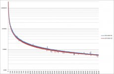 LCR-0202-33k-bypassed-100k-leak-A&B.jpg66 KB · Views: 64
 -
 LCR-0202-33k-bypassed-1k-leak-C&D.jpg69.8 KB · Views: 73
Log pot values for most used values in instrument amplification:
resistance = nominal value * (%Rot)^3.3
resistance = nominal value * (%Rot)^3.3
Code:
%Rot   250 k   500 k   1 M
0%   0,00   0,00   0,00
2%   0,00   0,00   0,00
4%   0,01   0,01   0,02
6%   0,02   0,05   0,09
8%   0,06   0,12   0,24
10%   0,13   0,25   0,50
12%   0,23   0,46   0,91
14%   0,38   0,76   1,52
16%   0,59   1,18   2,36
18%   0,87   1,74   3,49
20%   1,23   2,47   4,94
22%   1,69   3,38   6,76
24%   2,25   4,50   9,01
26%   2,93   5,87   11,73
28%   3,75   7,49   14,98
30%   4,70   9,41   18,81
32%   5,82   11,64   23,28
34%   7,11   14,22   28,44
36%   8,58   17,17   34,34
38%   10,26   20,52   41,05
40%   12,15   24,31   48,62
42%   14,28   28,56   57,11
44%   16,65   33,29   66,59
46%   19,28   38,55   77,11
48%   22,18   44,37   88,74
50%   25,38   50,77   101,53
52%   28,89   57,78   115,56
54%   32,72   65,44   130,89
56%   36,89   73,79   147,58
58%   41,42   82,85   165,70
60%   46,33   92,66   185,31
62%   51,62   103,24   206,49
64%   57,32   114,65   229,29
66%   63,45   126,90   253,80
68%   70,02   140,04   280,08
70%   77,05   154,10   308,19
72%   84,55   169,11   338,22
74%   92,56   185,11   370,22
76%   101,07   202,14   404,28
78%   110,12   220,23   440,47
80%   119,71   239,42   478,85
82%   129,88   259,75   519,50
84%   140,62   281,25   562,50
86%   151,98   303,96   607,92
88%   163,96   327,92   655,83
90%   176,58   353,16   706,32
92%   189,86   379,73   759,45
94%   203,83   407,65   815,31
96%   218,49   436,98   873,97
98%   233,88   467,75   935,50
100% 250,00 500,00 1000,00Updated code with mean value on analog readings to dampen the ripple:
Code:
#include <Wire.h>

//to manage the LCR-0202s
#include <Adafruit_PWMServoDriver.h>
Adafruit_PWMServoDriver pwm = Adafruit_PWMServoDriver(0x40);

//just to show results
#include <LiquidCrystal_I2C.h>
LiquidCrystal_I2C lcd(0x27, 20, 4);

//to read ambient temperature
#include <SimpleDHT.h>
int pinDHT22 = 2;
SimpleDHT22 dht22;
float temperature = 0;
float humidity = 0;

//analog readings in voltage dividers
int a_read[] = {0, 0, 0, 0};

//LCR-0202 initial resistance values
float LCR_ohm[] = {0, 0, 0, 0};

//define "leak" resistors in voltage dividers
unsigned long bottomR_ohm[] = {100000, 100000, 1000, 1000};

void setup() {
  //PWM startup
  pwm.begin();
  pwm.setPWMFreq(1500); //to avoid wavering of the light

  //LCD startup
  lcd.init();
  lcd.backlight();
  lcd.clear();

  // Serial startup
  Serial.begin(9600);
}

void loop() {
  for (int b = 0; b < 2; b++) {
    for (int i = 1; i < 4096; i += 64) {
      for (int led_num = 0; led_num < 5; led_num++) {
        pwm.setPWM(led_num, 0, (4095 - i));
      }
      read_values();
      show_values(b, i);
    }
    for (int led_num = 8; led_num < 13; led_num++) {
      pwm.setPWM(led_num, 0, (4095 * b));
    }
  }
}

void read_values() {
  delay(1000);
  dht22.read2(pinDHT22, &temperature, &humidity, NULL);
  for (int gpio = 0; gpio < 4; gpio++) {
    LCR_ohm[gpio] = 0;
    for (int num_read = 0; num_read < 1024; num_read++) {
      a_read[gpio] = analogRead(gpio);
      LCR_ohm[gpio] = LCR_ohm[gpio] + (((1023.00 / a_read[gpio]) - 1) * bottomR_ohm[gpio]);
    }
    LCR_ohm[gpio] = LCR_ohm[gpio] / 1024;
  }
}

void show_values(int b, int i) {
  lcd.clear();
  lcd.print("Robi's LCR-0202 Test");

  lcd.setCursor(0, 1);
  lcd.print("bit");
  lcd.print(b);
  Serial.print(b);
  Serial.print(", ");

  lcd.setCursor(6, 1);
  lcd.print("PWM");
  lcd.print(i);
  Serial.print(i);
  Serial.print(", ");

  lcd.setCursor(14, 1);
  lcd.print("T");
  lcd.print(temperature);
  Serial.print(temperature);
  Serial.print(", ");

  lcd.setCursor(0, 2);
  lcd.print(LCR_ohm[0]);
  Serial.print(LCR_ohm[0]);
  Serial.print(", ");

  lcd.setCursor(0, 3);
  lcd.print(LCR_ohm[1]);
  Serial.print(LCR_ohm[1]);
  Serial.print(", ");

  lcd.setCursor(10, 2);
  lcd.print(LCR_ohm[2]);
  Serial.print(LCR_ohm[2]);
  Serial.print(", ");

  lcd.setCursor(10, 3);
  lcd.print(LCR_ohm[3]);
  Serial.println(LCR_ohm[3]);
}
- Status
- Not open for further replies.