I have a set of potted output transformers, purportedly from a Sansui amplifier/receiver. They were touted by the Ebay seller as transformers compatible with EL84/6BQ5 outputs, which would place them at 8K optimum plate-plate impedance. As I usually do, I scoped out the primary leads (~400 ohms plate-plate, with a tap at 200 ohms - smells like a P-P transformer). I drove the 2 plate leads with a sine source at 50VAC, 300Hz, and got 0.905V out. This has me scratching my hard, as this indicates a turns ratio of 55:1, and a bona-fide 8k transformer would have a turns ratio of 31.6:1, and an output of 1.6 V or so when driven with 50V P-P. The turns ratio indicates 24k load at primary side with 8 ohm load. What were these transformers intended to do? They look good for about 15W apiece from the standpoint of size. Higher voltage input? Lower output impedance.? I hunted around on the secondary taps, and 0.9V or so is the most I can get out of them with 50V plate-plate drive on the primary side. Both transformers measure the same - head-scratching time...
That could be in the right ballpark for a stereo driving multiple speakers like a Magnavox did back then with a 2-3R output tranny impedance.
That sorta makes sense if there's one dedicated secondary (console/ organ amp?), but my transformers have tapped secondaries, with the tap putting about 1/2 the voltage of the the max output option. At least the P-P primary inductance is reasonable, at around 40-45H.
What did you use for reading the voltages? If it was a common DMM some of those have diminishing accuracy the higher the frequency above 60Hz. If so, try it again @100Hz. for the TR. Were you possibly reading 50V PEAK input signal but reading RMS at the outputs? You wouldn't use P-P voltage, it would be RMS IN/OUT or PEAK IN/OUT.
Last edited:
There are some single ended transformers with 22k primary impedance, like the Hammond 1750A. Could be there are some push-pull ones too.

Remember to measure the Rdc across the secondary, so that you'll know the Rdc losses when connecting different loads of 4R or 8R.
Also try measuring frequency response under these different loads. The lower the load, the more leakage inductance roll-off will kick-in.
Also try measuring frequency response under these different loads. The lower the load, the more leakage inductance roll-off will kick-in.
You're right, basically. But to take RDC losses into account, the turns (= no load voltages) ratio needs to be lower than the square root of Zprim/Zsec. The OP reports of higher turns ratio, anyway.Remember to measure the Rdc across the secondary, so that you'll know the Rdc losses when connecting different loads of 4R or 8R.
Best regards!
I drove the 2 plate leads with a sine source at 50VAC, 300Hz,
That's a heck of a sig. gen. What is that?
The most common Sansui stereo receiver that uses 6BQ5 is the Sansui 500A and it uses the beefy 7189A, which is wired differently than 6BQ5/EL84/7189. Below are schematics of various Sansui stereo receivers and one integrated amp. See if one of them matches your transformers. Keep in mind that some Sansui transformers have a 32-ohm tap. Please post pictures of your transformers.
SANSUI 500A
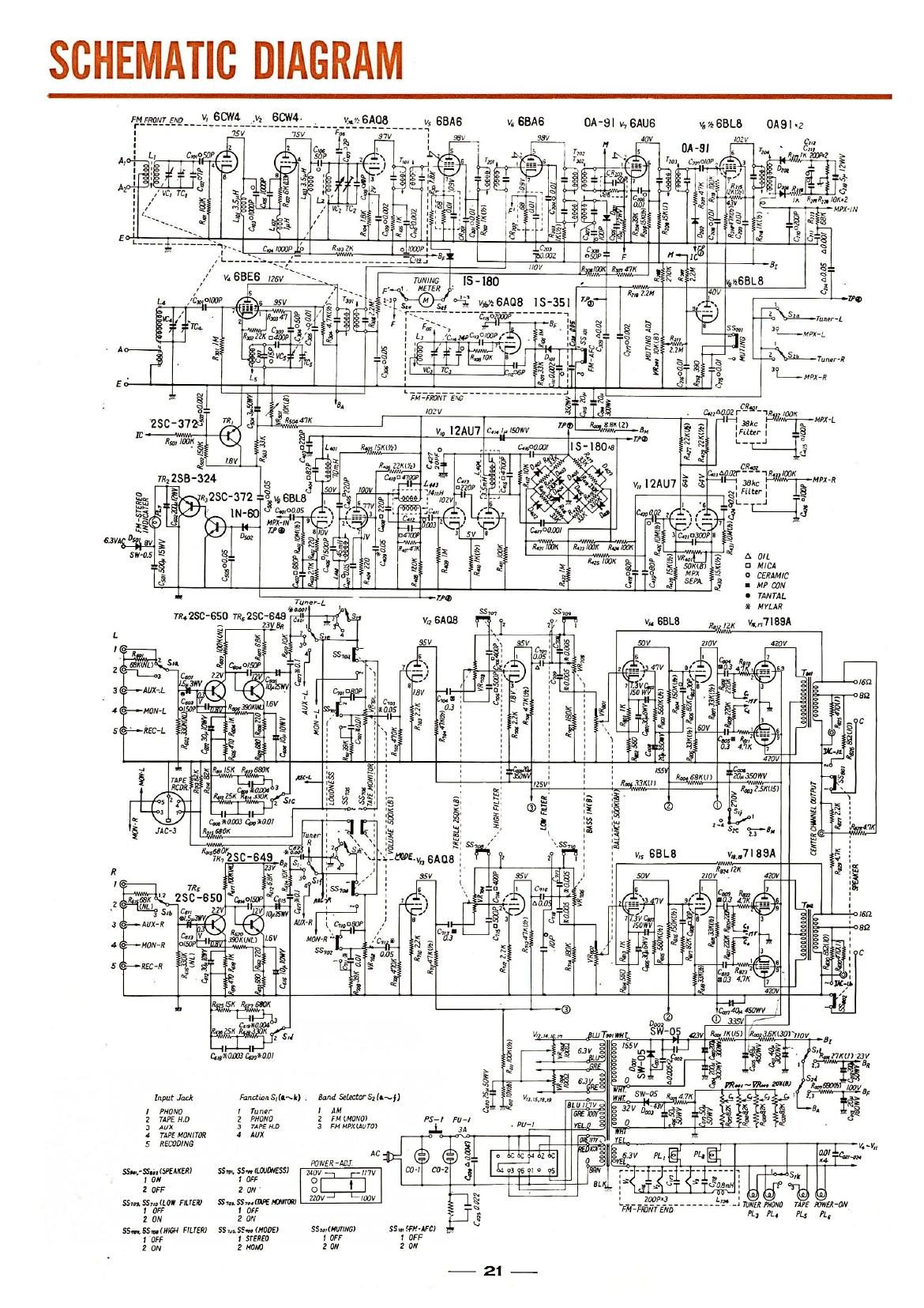
SANSUI SM-30

SANSUI SM-12

SANSUI 500

SANSUI AU-70

SANSUI 500A
SANSUI SM-30
SANSUI SM-12
SANSUI 500
SANSUI AU-70
The signal source I'm using to drive the transformer primaries is a Chroma 61504 AC source, a useful beast to have if you're in the business of evaluating SMPS. It features programmable output frequency. I use 300 Hz to drive the transformers to stay away from any low-frequency roll-off. I suppose 150-200Hz would work just as well.
I'll take pictures of the transformers when I have an opportunity. There's 3 leads on the primary side, and three on the secondary side. They are ugly and black - I intend to fix that when I get the opportunity to strip (a wire wheel works nice), re-prime and re- paint them. Metallic cast-iron gray works for me. I'll also post the numbers stamped on top of the transformers, though Google searches on those numbers haven't turned up anything of use.
Last edited:
I am measuring the turns ratio with secondaries unloaded, so I can also measure the exciting current and calculate the P-P primary inductance.
The signal source I'm using to drive the transformer primaries is a Chroma 61504 AC source, a useful beast to have if you're in the business of evaluating SMPS. It features programmable output frequency. I use 300 Hz to drive the transformers to stay away from any low-frequency roll-off. I suppose 150-200Hz would work just as well.
It looks like your Fluke can handle that 300Hz. easily. WOWZA on the Chroma... Makes me wonder if there's a bad coil section in the OPT. As an example, I had a Dynaco OPT that had an open interleaved parallel winding on one side and the only way to tell was the difference in DCR side to side. It worked in circuit but wasn't right. The bad side DCR was too high compared to another good OPT. So, ... you got a puzzler.. And if you have two giving you the same readings then I would think it's gonna take identifying them to the amps and the speaker options. I think a 3-4R tap, ala console, is not out of the question.
Last edited:
There is no problem with the DCR on the primary side. Both transformers measure about 400 ohms P-P, with what I presume is the center tap right in the middle at around 200 ohms. Primary inductance is about 45H on one, and about 39H for the other. This is part of the investigation I perform on any unknown push-pull transformer to find out which are the plate leads, and which is the center tap, so I know which two leads to drive.
Just to try a different measurement technique in case there is some hidden flaw we don't notice: if you have an SS amplifier available, basically "anything", which can put out, say, 15/20 V RMS, drive it just below clipping with different frequencies, say 100 - 400 - 1000 Hz, both plate to plate and each plate to primary center tap, and measure all 3 secondary tap combinations: end to end and each end to their CT.
You might find exact same results as before or have a "what the hell?" moment.
It will take less than an hour to setup and test and it "might" show something.
Remember Murphy's Law, "sh*t happens", etc 🥴
Take notes of every measurement and post results.
You might find exact same results as before or have a "what the hell?" moment.
It will take less than an hour to setup and test and it "might" show something.
Remember Murphy's Law, "sh*t happens", etc 🥴
Take notes of every measurement and post results.
While DCR values of primary halves sometimes differ, inductance values should be the same because of same turns' number.There is no problem with the DCR on the primary side. Both transformers measure about 400 ohms P-P, with what I presume is the center tap right in the middle at around 200 ohms. Primary inductance is about 45H on one, and about 39H for the other.
How did you measure?
- Home
- Amplifiers
- Tubes / Valves
- Puzzling Set of Output Transformers