There, a PCL84 PP monoblock schematic I've been wanting to try for quite some time now, the schematic somebody posted short while ago utilizing 100V line transformer as OPT reminded me of these plans. This shoud provide up to 3W (without driving tubes above suggested maximum dissipation line) with fairly conservative supply of 160V AC and 200 mV peak to peak input (70 mV RMS). It's supposed to serve as a guitar practice amplifier.
Now my question is: is the input sensitive enough for electric guitar pickups ? I've seen references stating that pickup coils will output anything from 100 mV upwards (I take this is meant as peak to peak value 😕 ), however since I don't own a guitar I cannot verify this claim.
I'm going to use a 10W 100V OPT for output in class AB. PCL84/ECL84 tubes are just as cheap to buy as the OPT was so I designed this whole amplifier to be built only with easily affordable parts - aside from power transformer (I recycled it from another project) this thing shouldn't cost me more than 20 EUR ($30 USD) to build, and not more than 40 EUR ($50) with mains transformer(s) included. I also have some salvaged large diameter speakers which will fit perfectly into the box for series 8R load.
I haven't decided on whether I really want to incorporate the UL/pentode switch (I might just pick one option after initial testing and dump the switch).
If supply voltage was increased to 300V, more power (up to 4.5W) could be extracted without grossly violating those pentode sections.
Comments welcome ! 🙂
Attachments
Now my question is: is the input sensitive enough for electric guitar pickups ? I've seen references stating that pickup coils will output anything from 100 mV upwards (I take this is meant as peak to peak value 😕 ), however since I don't own a guitar I cannot verify this claim.
No, it isn't. You need another gain stage and if your friend likes to play metal/hard rock it won't be enough either. Maybe a good idea would be to use a pentode.
I see. What kind of input sensitivity should I be aiming for (for maximum output swing) ? Noise will become an issue with insanely high amplification levels 🙁
Yes, je plays hard rock (Metallica and the like). He has two guitars (and a bass guitar), but I won't have access to either until this is finished.
Yes, je plays hard rock (Metallica and the like). He has two guitars (and a bass guitar), but I won't have access to either until this is finished.
I see. What kind of input sensitivity should I be aiming for (for maximum output swing) ?
Depends on his pickups, whether he uses humbuckers or single coils. 100 mV to stay on the safe side but remember that preamp distortion may be desirable. Guitarists also love tone controls. You better check some schematics out.
Schematic Heaven. Where All Good Amp & Effect Designs Await Resurrection...
Both are humbuckers (double coils), I'm not sure about the bass guitar though.
Am I correct in assuming that humbuckers give twice the output swing of a single coil (due to series connection of both coils) with the additional benefit of common mode noise cancellation that they are mainly used for ?
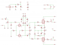
Hm, short by a factor of 3-4x for plenty of overdrive, this is dissapointing to say the least 🙁 PCL84 consists of rather high mu triode (65) and a very sensitive pentode so I was hoping to get away with the two tube setup to the max. of their capability. I could cheat up 1.5x more voltage amplification with CCS load on the triode but I really wanted to keep away from sandy devices (except with diodes, of course) and at the same time get away with the ~15V parallel heating since I have the transformer handy from another project (16V, hence the dropping resistor in series with the filaments).
I'll have to think it over once more, I might just add another PCL84 for two additional cascaded gain stages and revert to LTP phase splitter to offset extra gain. Perhaps one section could be used as some sort of effect (tremolo oscillator) instead ?
Am I correct in assuming that humbuckers give twice the output swing of a single coil (due to series connection of both coils) with the additional benefit of common mode noise cancellation that they are mainly used for ?
Hm, short by a factor of 3-4x for plenty of overdrive, this is dissapointing to say the least 🙁 PCL84 consists of rather high mu triode (65) and a very sensitive pentode so I was hoping to get away with the two tube setup to the max. of their capability. I could cheat up 1.5x more voltage amplification with CCS load on the triode but I really wanted to keep away from sandy devices (except with diodes, of course) and at the same time get away with the ~15V parallel heating since I have the transformer handy from another project (16V, hence the dropping resistor in series with the filaments).
I'll have to think it over once more, I might just add another PCL84 for two additional cascaded gain stages and revert to LTP phase splitter to offset extra gain. Perhaps one section could be used as some sort of effect (tremolo oscillator) instead ?
Hi Arnulf
Is there any special reason to implement D1 and D2? I have never seen diodes in that position before.
erik
Is there any special reason to implement D1 and D2? I have never seen diodes in that position before.
erik
Oh, it's just for power-up, diodes are still cheaper than ruined output tubes 🙂 At power-up voltage at grids of pentodes will rise abruptly, then it will decline when triode cathodes start with emission and triodes begin conducting. Diodes clamp this voltage to 0.7V (in place of almost full B+ on g1), but are reverse biased during normal operating (g1 never gets more positive than -1V in normal operating this this design so there's 1.7V of headroom before diodes would clip) so they are out of circuit and its tiny capacitance is irrelevant in audio band.
You can leave them out as far as circuit is concerned, it will work just as well once everything heats up.
You can leave them out as far as circuit is concerned, it will work just as well once everything heats up.
.
Am I correct in assuming that humbuckers give twice the output swing of a single coil (due to series connection of both coils) with the additional benefit of common mode noise cancellation that they are mainly used for ?
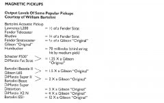
No, the kind of magnet used and number of turns (DC resistance) is what really matters. A hot pickup has a DC resistance of 10K or more. 100 mV pickups have around 6K. Having said that, humbuckers are generally louder but not always. You're right about the common mode noise cancellation.
I've just checked a 2010 Fender schematic and the input sensitivity is 25mV. Two inputs, one using a voltage divider for hot pickups.
Attachments
Oh, it's just for power-up, diodes are still cheaper than ruined output tubes 🙂 At power-up voltage at grids of pentodes will rise abruptly, then it will decline when triode cathodes start with emission and triodes begin conducting. Diodes clamp this voltage to 0.7V (in place of almost full B+ on g1), but are reverse biased during normal operating (g1 never gets more positive than -1V in normal operating this this design so there's 1.7V of headroom before diodes would clip) so they are out of circuit and its tiny capacitance is irrelevant in audio band.
You can leave them out as far as circuit is concerned, it will work just as well once everything heats up.
Hi Arnulf
Thanks for the explanation!
Erik
I've just checked a 2010 Fender schematic and the input sensitivity is 25mV. Two inputs, one using a voltage divider for hot pickups.
Uh-huh, another tube it is then. This throws a big monkey wrench into my neatly planned PCB but there's no other way around it. I'm considering either another PCL84 or PCC88.
Hey Arnulf,
I have replaced the input EF86 in all our reVintage-Amps with a cascoded E88CC. Works great and is easily available. To make it sing for guitar it should run with as low current as the EF86.
If you add a Tweed Deluxe volume/tone between power amp and inputstage you´ve got it all.
I have replaced the input EF86 in all our reVintage-Amps with a cascoded E88CC. Works great and is easily available. To make it sing for guitar it should run with as low current as the EF86.
If you add a Tweed Deluxe volume/tone between power amp and inputstage you´ve got it all.
Last edited:
Yep, thats the one.
Here is the original Amp Guide » Fender*Deluxe (Narrow Panel)
Don´t change the paraphase PI "Gibson GA-40 Style" poweramp.
Here is the original Amp Guide » Fender*Deluxe (Narrow Panel)
Don´t change the paraphase PI "Gibson GA-40 Style" poweramp.
Last edited:
Go for the Fender! The Gibson is dull. But try the Fender first and change to Gibson later if you don´t like it.
Suppose you mean the "real" GA-40 Les Paul with the tone-control inside the poweramp.
Vox AC-30 used that one later.
Suppose you mean the "real" GA-40 Les Paul with the tone-control inside the poweramp.
Vox AC-30 used that one later.
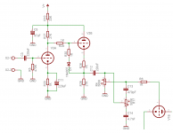
The E88CC wont work well unless you go cascode. The component values should be close to a std EF86 stage. You can add a MOSFET like DN2540 SF if you want.
What would be the problem with only one triode amplification stage ?
I lowered B+ to safe level (130V), Va(q) = 80V, plus I like the idea of cathode follower running whatever tone stack this ends up with. With gain Av = 20 of the additional stage input sensitivity of the amplifier drops down to less than 10 mV for full output power, anything over that and output stage will compress heavily due to G2 current anyway.
No sand except diodes 😉 Otherwise I could simply slap in opamp phase inverter and get rid of additional tube (plenty of gain to be had from the section that serves as paraphase now).
That would be up to 3 tubes again for PP output (barring something like QQE03/12 which I don't have anyway) plus I have those PCL84s left over and nothing else to use them for at the time being. They have higher heater power requirement than E/PCL82 or E/PCL86 and rather low driving requirements for full output swing so I had to do come up with something other than yet another headphone amplifier which nobody I know would have any use for. I'm saving the Earth by recycling them in this manner, you see 😀
- Status
- Not open for further replies.
- Home
- Amplifiers
- Tubes / Valves
- Push-pull PCL84 schematic and a question