Hi. I`m looking for push pull designs to use with the iron i have sitting here under my desk. I have built a couple of Bottlehead kits and the VTV octal so i can read a schematic and solder but i can`t design an amp from scratch. My speakers are around 88db so i figure 20 watts and up should suffice.
Also i am tryng to keep the cost to a reasonable level so 300bs are out. I have a pair of Hammond 300bx power trans, 2 193j [10h 250ma] chokes and a pair of Magnaquest 431 outputs.
I also have built a pair of monoblock chassis ready to go. I just need a schematic with power supply for el34,kt88,6550,el84 or whatever you think would work and sound good.
Thanks, Steve.
castlesteve said:or whatever you think
I think you need to tell us the specs of those transformers you have. 😉
Tim
The MQ431 O/P trafo is an upgraded "copy" of the unit used in the Dyna MK3. That tells us that it is suited for use with 6550/KT88/KT90 tubes.
You could "clone" the Dyna MK3, but I think you can do much better. Take a look at the "Dusty Files" on Triode Electronics' site (www.triodeelectronics.com). A pet idea of mine for PP amps is to use a differential (Schmidt) phase splitter with a CCS in its tail in front of the "finals". That arrangement allows the NFB to be applied to the inverting I/P of the splitter. The advantage of the arrangement is that the NFB loop is around 2 stages, rather than global. Shorter IS better. Place whatever linear voltage gain circuit that tickles your fancy in front of the splitter.
You could "clone" the Dyna MK3, but I think you can do much better. Take a look at the "Dusty Files" on Triode Electronics' site (www.triodeelectronics.com). A pet idea of mine for PP amps is to use a differential (Schmidt) phase splitter with a CCS in its tail in front of the "finals". That arrangement allows the NFB to be applied to the inverting I/P of the splitter. The advantage of the arrangement is that the NFB loop is around 2 stages, rather than global. Shorter IS better. Place whatever linear voltage gain circuit that tickles your fancy in front of the splitter.
Push pull designs
Thanks for the replies guys. Eli. I`m not technically savvy enough to understand all of what you wrote. I`m looking for a good design to use as i don`t yet understand enough to design my own amp.
The output transformer is rated 60watts at 4300 0hms and is as Eli stated an upgrade for the Dynaco mk111. The power trans is rated 400-0-400 at 250ma.
Thanks, Steve.
Push pull designs
Or this: http://www.ptsoundlab.com/sectubes/schemas/el34/25WPP/blocmono25wppel34.htm
Or this: http://www.ptsoundlab.com/sectubes/schemas/el34/25WPP/blocmono25wppel34.htm
Steve,
The KT88 circuit (Plitron link) has promise. You could substitute the electrically equivalent Locktal based 14N7 for the 6SN7s. Constructing a 12 VDC heater supply for 14N7s is easy and a nice way to reduce the hum level. Prices for NOS 6SN7s are high, but good things are being said about current production EH 6SN7s. Jim McShane (Mr. H/K Cit. 2) likes the EH KT88. I suggest you acquire a set of burned in EH KT88s from JM.
I've got some serious reservations about the power trafo you have. Is that 250 mA. rating for DC draw with a cap. I/P filter or is it the max. AC RMS current. If, as I suspect, it's the AC RMS current, you need a 2nd identical power trafo. In any event, building monoblocks is a good idea. I can tell you from personal experience that a stereoblock PP KT88 amp is heavy, as I own a H/K Cit. 2.
BTW, you don't need the bias meter. The 10 Ohm cathode resistors provide a useful test point. Measure the voltage drop across the resistor. Ohm's Law allows you to easily calculate the idle current of the tube.
Power supply side
The Hammond power xfmrs will perform ok on monoblocks, but are somewhat current & voltage limited. To get in the range of 400 volts using a 5AR4 rectifier tube, the filter must be a input capacitor design or a CLC in your design. I would limit that input cap to 20uF & not exceed 175madc. I would guess Hammond would conservatively derate to 150madc with capacitor input.
The Hammond power xfmrs will perform ok on monoblocks, but are somewhat current & voltage limited. To get in the range of 400 volts using a 5AR4 rectifier tube, the filter must be a input capacitor design or a CLC in your design. I would limit that input cap to 20uF & not exceed 175madc. I would guess Hammond would conservatively derate to 150madc with capacitor input.
push pull designs
I do have a pair of the 300bxs as i was planning on monoblocks all along. Does anyone have any other schematics worth considering?
Steve.
I do have a pair of the 300bxs as i was planning on monoblocks all along. Does anyone have any other schematics worth considering?
Steve.
Steve,
With 2 power trafos, you are good to go. 400 VRMS is approx. 565 V. peak. The drop across the vacuum in a 5AR4 is low. You should be fine for a 525 V. B+ rail. A CLCRC filter where R is adustable should let you dial the rail voltage in. The suggestion to use 20 muF. in the 1st cap. position is EXCELLENT. 20 muF. is plenty to keep the rail voltage up, while holding down I^2R heating in the power trafo. Jim McShane is a source for properly tested Chinese 5AR4s that will not bust the budget. The NOS option for the rectifier is the Mullard made GZ33; while not low cost, its price is a LOT less than a NOS 5AR4/GZ34.
Use the 3 A. 5 VAC winding to energize the 5AR4 heater. Tie the 1.2 A. 5 VAC winding off. The 6 A. 6.3 VAC winding is "beefy" enough to energize all 4 signal tube heaters.
Locktal 7N7s are the low cost NOS option for the small signal tubes. If you want an all Octal amp, use the EH 6SN7 in the small signal positions.
Simple half wave rectification of the 50 VRMS bias tap is not sufficient to get the bias rail you need. 50 VRMS is approx. 70 V. peak. Therefore, a voltage doubler is required. The O/P of the doubler will be well over 100 VDC.
BTW, Ron Welborne has kits for regulated PSUs (B+ and bias) to be used in overhauling Dyna MK3s. While Welborne's PSU uses SS rectification, it also includes a soft start for the B+. Check in with Ron and see if his stuff can be used in this project. If it can, the 3 A. 5 VRMS winding could be used to energize a voltage doubler that feeds a low drop out regulator. You would have the 12 VDC at sufficient current needed to use 14N7s in the small signal positions.
PPP 807
I would try parallel push-pull RCA 807s in triode connected. I have seen a data sheet with 400 volts on the screens as tied to the plates with 100 ohm resistor, h0owever specs state 300 volts screen. Another post states sounded triode RCA 807s sounded like like PP 300Bs, but I can not verify that.
The good point about the 807s are inexpensive quality 1940s stock is available from a lot of suppliers & ebay- very common tube.
As for that 525 volt rail? The 400 volts out is using full-wave center tap with 5AR4 and input capacitor as simulated on the PSU Designer II power supply designer with a simulated load of 175 ma.
Opps
That PSU II simulator was with a 600 VCT secondary.
Being your xfmr is 800VCT volts, that 525v is correct. Redoing that calculation with a 5U4GB reduces the voltage to a more acceptable 450 volts. With that said, try this schematic at www.tubebuilder.com/schematic1.html
It is the 6DJ8 differential input to a 6SN7 to 300Bs. replace the 300Bs with a triode straped pentode such as four 807s , or perhaps a pair of 6550s. Having experience using 6DJ8 and 6SN7, I prefer Amperex 7308 gold pin & Sylvania 6SN7GT with the 'T' plates.
If you like that 6DJ8/6SN7 design.......
As a reminder, the 450 ohm cathode resistor must be recalculated for other tubes than the 300Bs.
As a reminder, the 450 ohm cathode resistor must be recalculated for other tubes than the 300Bs.
Re: PPP 807
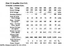
Below is a clip from the STC807 dtatsheet for class A tetrode for one pair of tubes.
They don't sound like 300B's. But they are very good, and as you said, there are tons of good vintage NOS stock.amperex said:I would try parallel push-pull RCA 807s in triode connected. I have seen a data sheet with 400 volts on the screens as tied to the plates with 100 ohm resistor, h0owever specs state 300 volts screen. Another post states sounded triode RCA 807s sounded like like PP 300Bs, but I can not verify that.
The good point about the 807s are inexpensive quality 1940s stock is available from a lot of suppliers & ebay- very common tube.
Below is a clip from the STC807 dtatsheet for class A tetrode for one pair of tubes.
Attachments
807
I am building that 6DJ8 to 6SN7 to triode connected PPP 807s. I'll use cathode bias and 440 volts B+ with about 400 volts plate to cathode on the 807s. Although a pair shows up on tube data sites with 3000 ohm anode to anode for a pair, I will use 4300 ohms anode to anode for four tubes.
I am building that 6DJ8 to 6SN7 to triode connected PPP 807s. I'll use cathode bias and 440 volts B+ with about 400 volts plate to cathode on the 807s. Although a pair shows up on tube data sites with 3000 ohm anode to anode for a pair, I will use 4300 ohms anode to anode for four tubes.
Thanks for all of your help guys. I think i`m going to go with a pair of EH Kt88 monos with 6SN7s in the first stage. I`ll let you know how i`m proceeding.
Jan,
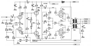
A nice simple circuit - simple circuits have simple problems - simple problems have simple solutions - therefore I like it.
In a light hearted sense - here is your design review:
1) I don't like the resistor capacitor across the two anodes of the fist differential stage - separate series resitor and capacitor network across each anode load is reputed to better.
2) Should you ever contemplate using anything other than EL34 then the R8,P2,R12 (and the similar network on the other side) needs modification to reduce total grid circuit resistance. This combination is giving about 250K Ohms (at DC) from grid to 0V. For KT88 or similar you want to get this down to at least half - that is not more than say 120K - the driver stage will cope with this OK.
3) Unless you are running pure Class A - which I don't think you are, you should probably bypass R16 with say a 470UF to 2200uF high quality electrolytic (a Blackgate or Nichicon Muse etc.)
4) C7 and C8 could benefit from a 100nF film cap across them. Very occassionally this may introduce slight ringing - if so put 1 Ohm in series with the film caps. (Polyester would be fine - no need to go to polypropylenes).
Otherwise I give you a 9 out of 10. Congratulations.
Cheers,
Ian
- Status
- Not open for further replies.
- Home
- Amplifiers
- Tubes / Valves
- Push pull designs.