Hi all,
Apologies if this is better suited for the Software Tools forum, but it's specific to vacuum tubes.
Can anyone provide or point me to an example of how to set up a circuit in LTSpice to generate the composite curves for two tubes in push-pull? I can generate the curves just fine for SE circuits, but I just can't figure out how to do it for PP circuits.
I've looked around for examples, and the only one I could find was by posted 15 years ago by John Podesta. Unfortunately, his example is for command-line Spice 3, so there's no schematic. I've tried reading his netlist, but I'm having a hard time identifying some of the components and how they are connected to each other.
Thanks, nice trick.
Dmitry Nizhegorodov's page 3.4 is helpful.
Use bv (arbitrary voltage source) in ltspice,
but some how, ltspice does like v(vg) in bv ...
I have to use the numerical node number like v(n002) in bv !
Dmitry Nizhegorodov's page 3.4 is helpful.
Use bv (arbitrary voltage source) in ltspice,
but some how, ltspice does like v(vg) in bv ...
I have to use the numerical node number like v(n002) in bv !
I can't see it's possible in LTspice, Dmitry is using Pspice it seems to run 2 instance of .DC.
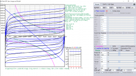
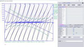
But pp loadline is found in the paint tools PainKIT (triode) and PaintKip (Pentode).
The good thing is you can paste any working model into the text window by clicking on Model and then Update params, you have completed model. Then select PP in Loadline and other icon, it is all interactive.
The other online tool is Universal loadline calculator for vacuum tubes - Vacuum Tube Amplifiers - DIY
Attachments
Got it working after the component attributes changed to "B" otherwise it wouldn't work. Thank you very much.
Instead of using V(n002), can use V(in) where "in" is the label port name to replace V(n002).
Instead of using V(n002), can use V(in) where "in" is the label port name to replace V(n002).
Attachments

Last edited:
:: View topic - plotting loadlines in spice
:: View topic - Generic push-pull loadline
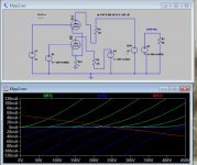
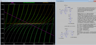
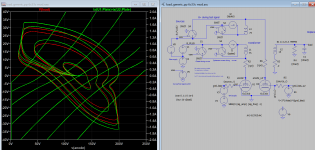
Above is another approach: transient analysis for curves as well as transformer amplifier output. you can download it, remember to set the Horizontal axis to V(anode) or time for it to display correctly.
I have made a simplified version, and it's comparable to previous version using .DC analysis, but curves tracer generator is much more complex, and a bit difficult to set the bias voltages begin from 0. Feel free to comment on the correctness of simulations.
:: View topic - Generic push-pull loadline
Above is another approach: transient analysis for curves as well as transformer amplifier output. you can download it, remember to set the Horizontal axis to V(anode) or time for it to display correctly.
I have made a simplified version, and it's comparable to previous version using .DC analysis, but curves tracer generator is much more complex, and a bit difficult to set the bias voltages begin from 0. Feel free to comment on the correctness of simulations.
Attachments
-
 load_generic_pp simple2 6c33c-2.png91.6 KB · Views: 209
 -
 load_generic_pp simple2 6c33c-1.png144.6 KB · Views: 215
 -
 pp looadline 6c33c-1.png119.8 KB · Views: 141
 -
load_generic_pp simple2 6c33c.asc4.6 KB · Views: 112
-
pp loadline.asc2.9 KB · Views: 79
-
 loadline pp 6c33c Paint-1.png319.8 KB · Views: 156
Last edited:
I don't think the sine and the steps functions matters
in DC analysis.
I had trouble with your load_generic_pp simple2 6c33c.asc
doing DC sweep. Ltspice complains "previous analysis already found."
So I used sbench's schematic to validate my claim. I may be wrong.
I *think* sbench intent of these examples is to show
how the same schematic can be used for both DC and transient
analysis by using a switch.
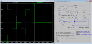
"previous analysis already found." There maybe another analysis found, I found very few info on this case using Google. Sine wave is strictly not a straight curve but ellipse curve you can see when zoom in. But what I meant is you verified my sim before using it, not to compare on the accuracy of approaches separate, is there another approach?
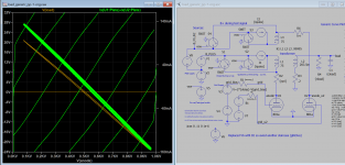
I deleted the 801a model directive on the bottom left corner, the error no longer appeared and it seems to work with .DC sweep at the V2 voltage source and give a perfect straight curve line! So V3 stepping is working.
It is a push-pull transient analysis plotted as IV curve.
Very very nice !!
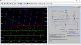
What I said in post #9 is incorrect.
I modified your drawing just a little bit,
I've also include a plot file for the sake of completeness.
Rename
load_generic_pp_6c33c.txt
as
load_generic_pp_6c33c.plt
to use it in ltspice.
Very very nice !!
What I said in post #9 is incorrect.
I modified your drawing just a little bit,
I've also include a plot file for the sake of completeness.
Rename
load_generic_pp_6c33c.txt
as
load_generic_pp_6c33c.plt
to use it in ltspice.
Attachments
I hope this is what you meant the actual purpose: comparing (the tilting of) input and output freq response. The article is worth reading, but unfortunately colors are not readable.
http://www.samhallas.co.uk/repository/po_docs/ep_electronics_2_7.pdf
http://www.samhallas.co.uk/repository/po_docs/ep_electronics_2_7.pdf
Attachments
Last edited:
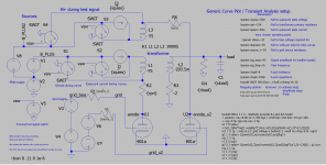
Here is 6c33c version, replaced V6 with B1 as fossa indicated. The settings are differences from 801a, you have to adjust several times to get it working correctly. I haven't modified others because it might have glitches here and here but feel free to improve it.
Attachments
- Home
- Amplifiers
- Tubes / Valves
- Push-Pull Composite Curves in LTSpice?