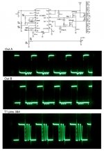
I've just started experimenting with SMPS circuits by trying to build a DC-DC converter with six isolated outputs using an existing transformer. The circuit, so far, is shown below. The waveforms have me puzzled. It's almost as though the A side of the primary is open. I'd appreciate any thoughts or ideas.
BTW, I've searched and browsed, but haven't found anything quite like this.
Regards,
Don
BTW, I've searched and browsed, but haven't found anything quite like this.
Regards,
Don
Attachments
It looks pretty much like the thing is working to me...
The T1 output waveform shows the transformer response to (in sequence) - Output B drive, followed by a deadband, followed by Output A drive, then Output B drive, deadband, OutputA drive, and so on.
The heavy ringing occurs when both mosfets are off (deadband).
Cheers
The T1 output waveform shows the transformer response to (in sequence) - Output B drive, followed by a deadband, followed by Output A drive, then Output B drive, deadband, OutputA drive, and so on.
The heavy ringing occurs when both mosfets are off (deadband).
Cheers
The control circuit is not working properly because the gate drive pulses don't follow a valid pattern, they should be evenly spaced and should look like: OUTA-deadtime-OUTB-deadtime. I think that it has to do with the way in which you have wired the error amplifier. If you want to adjust the duty cycle with a potentiometer, see how it's done in the test circuit from the datasheet. Essentially the error amp has to be wired as an unity gain follower and the potentiometer has to be set up to apply 0.5V to 4V to the non inverting input (sawtooth range: 0.9V to 3.5V plus 0.5V more at each end). If you apply less than 0.5V to any of the inputs, the error amp will latch up, so additional resistors are required between the potentiometer and ground and Vref in order to obtain the right adjustment range.
Also, you should tie the SYNC input to ground if you are not using it because it could be false triggered otherwise, and you should use a proper soft start capacitor value like 1uF to avoid core saturation at power on.
Also, you should tie the SYNC input to ground if you are not using it because it could be false triggered otherwise, and you should use a proper soft start capacitor value like 1uF to avoid core saturation at power on.
That is reassuring!
Chem_o - I'm glad to hear that the ringing during deadtime is normal. I was afraid it was a symptom of a circuit problem.
Eva - I had the pot in for testing, so I'll wait to see how the output looks after I finish the feedback circuit. I'll follow your advice on the sync and soft start, too.
Thank you both for the quick responses and advice.
-Don
I think it will quiet down a bit once the rest of the (correct) circuitry is in... I'm pretty much a newbie when it comes to smps - Eva is the expert!!
Cheers
Cheers
I would try to sort out the duty cycle thing and the non-coherent output pulses problem before doing anything else.
Progress Report
Well, it's working pretty well since I added the feedback components. Eva, just so you know, that unused pin on this controller (MC34025) isn't the same as the "sync" input of the SG3525. I would think that grounding it would effectively disable the oscillator.
Regards,
Don
Well, it's working pretty well since I added the feedback components. Eva, just so you know, that unused pin on this controller (MC34025) isn't the same as the "sync" input of the SG3525. I would think that grounding it would effectively disable the oscillator.
Regards,
Don
- Status
- Not open for further replies.
- Home
- Amplifiers
- Power Supplies
- Push-Pull Circuit