It’s a USB powered device, the series capacitors are there to keep everything downstream isolated.
The shunt network appears to be an output zobel or something similar.
The shunt network appears to be an output zobel or something similar.
Blocking capacitors are needed to block the DC at the output, this being a single supply device.
The mfr usually knows best, since they designed the device.
The mfr usually knows best, since they designed the device.
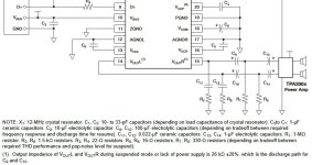
In the diagram both DAC and amplifier have single power supply, meaning there is a DC bias at the output of the DAC and input of the amp. And to prevent case when one of the caps is reverse-biased, there are two DC-blocking cap in series. If you notice, they have positive terminals connected to IC (DAC/amp) because the DC bias is positive at IC terminals.
The RC's are just for low pass fitering, you still need a reconstruction filter.
Film caps are non-polar so you can.
The RC's are just for low pass fitering, you still need a reconstruction filter.
Film caps are non-polar so you can.

The RC snubbers squash RF noise on the lines, the CRC stage keeps the output quiet when the DAC is powered down I think - the suspend function?
Its a classic problem with cheap DACs that when they turn off the output floats, providing an audible jump in the noise floor. The 330R to ground will stop this. Its unfortunate so many electrolytics are needed, and they probably should be higher in value than recommended too to preserve the bottom octave.
Its a classic problem with cheap DACs that when they turn off the output floats, providing an audible jump in the noise floor. The 330R to ground will stop this. Its unfortunate so many electrolytics are needed, and they probably should be higher in value than recommended too to preserve the bottom octave.
Thank you all for explanations!
If my headphone amp already has LPF and HPF can I remove R5C11 and R6C12?
If the noise when turning off does not bother me, can I delete C9, C10, C13, C14, R7, R8 (my headphone amp already has 2.2uF film caps at input)?
If they cannot be removed, then what value should the 100 uF capacitors be replaced with? Will 2200 uF be enough?
The RC snubbers squash RF noise on the lines
If my headphone amp already has LPF and HPF can I remove R5C11 and R6C12?
CRC stage keeps the output quiet when the DAC is powered down
If the noise when turning off does not bother me, can I delete C9, C10, C13, C14, R7, R8 (my headphone amp already has 2.2uF film caps at input)?
If they cannot be removed, then what value should the 100 uF capacitors be replaced with? Will 2200 uF be enough?
The 330 load resistors might be useful to get minimum distortion too - that's what the datasheet implies I think. But they need one set of capacitors if so - the second set of caps isn't needed if the load already is capacitively coupled.
Perhaps add the pads for these components, you don't have to populate them all..
Perhaps add the pads for these components, you don't have to populate them all..
- Home
- Design & Build
- Electronic Design
- purpose of resistors and capacitors in DAC PCM2704C audio output