Hi! I have a punch 851s, it comes with the lm317 shortcircuit. Replace it and again in short. Find d3 in short and replace it, im testing with a lm7815 for the moment.
I pull out all output mosfets, all are ok. Rail caps out of the board for test.
I have +- 47 volts on rail. -20v on 640 gates and +20 v on 9640 gates, so if i put one and one the ps shuts off, both are on at the same time.
The first problem with the lm317 in short was +47 volts instead of +20 volts on the control circuit. 4 47ohm resistors replaced because the high voltage. All 1am and 2a and 1q smd transistor are ok. Bias pots 2k ohm readings are ok. A56 and a06 ok.
I have the 800a2 schematic, are the same board.
Any ideas?
With any of the components inside the feedback loop out of the circuit (including the outputs), you cannot use the voltages for troubleshooting.
Reinstall the outputs, set the bias pots fully CCW and power the amp up through a limiter. Does it power up?
Reinstall the outputs, set the bias pots fully CCW and power the amp up through a limiter. Does it power up?
One channel installed, 2 1am transistor replaced, q301 and q207. Now the ps only does 14v, no dc voltage at speaker terminals
Are you saying that the rail voltage won't go above 14v?
What are you using for a 12v power supply?
How much current is thew amp drawing?
Did you set the bias pots fully CCW after replacing the parts?
What are you using for a 12v power supply?
How much current is thew amp drawing?
Did you set the bias pots fully CCW after replacing the parts?
Bias fully ccw, 20amp ps for test. Nothing above 14v.
With the 9640 source resistors desoldered the ps does 47 volts but i have heat from lm regulator and q304, q305 and q307.
With the 9640 source resistors desoldered the ps does 47 volts but i have heat from lm regulator and q304, q305 and q307.
If you powered the amp up with the source resistors out of the circuit, you likely damaged the protection circuit.
Do you have a 2 ohm limiting resistor?
Is that ±14v or just 14v?
Do you have a 2 ohm limiting resistor?
Is that ±14v or just 14v?
23 amp ps with shortcircuit protection so it protects itself, any amp burned with this ps.
I have -46 volts on the irf640 and -46v on the gates so all are off.
46volts on the 9640 and 20v on gates, so are all on and i have 46volts at output.
The amp ps its working fine +-46 volts. +-20 volts from lm337 and 317.
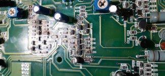
Lm317 gets warm and the area in the picture. The ps protects after 5 or 6 seconds.
-
I have -46 volts on the irf640 and -46v on the gates so all are off.
46volts on the 9640 and 20v on gates, so are all on and i have 46volts at output.
The amp ps its working fine +-46 volts. +-20 volts from lm337 and 317.
Lm317 gets warm and the area in the picture. The ps protects after 5 or 6 seconds.
-
Attachments
any ideas??
the q229 had 46 volts on the collector, 20v at the base and 20 volts on the emmiter, so all irf9640 mosfets are on all time.
double checked q226, q227, q228, all the control area, everything seems ok.
the q229 had 46 volts on the collector, 20v at the base and 20 volts on the emmiter, so all irf9640 mosfets are on all time.
double checked q226, q227, q228, all the control area, everything seems ok.
FETs don't have base, collector, emitters.
If you have the same voltage on the gate and source, the FET is not on.
If you have the same voltage on the gate and source, the FET is not on.
Q229 is a mpsa06, that controls the gate of the irf9640
With 20 volts at the base only pass 20 volts from the 46 volts on the collector to the emmiter. With 20 volts at gates of the fets irf9640 they are on. Needs 46 volts at gate to turn off.
With 20 volts at the base only pass 20 volts from the 46 volts on the collector to the emmiter. With 20 volts at gates of the fets irf9640 they are on. Needs 46 volts at gate to turn off.
I replace all small smd transistors at.the control, some.and 06.
Now the irf9640 have 47 volts at the gate so they are off, both channels. Now the irf 640 have -20 volts atthe gates and the output have -47 volts all time.
The problem is solved at 9640's and is present at 640's. Both channels same problem
Now the irf9640 have 47 volts at the gate so they are off, both channels. Now the irf 640 have -20 volts atthe gates and the output have -47 volts all time.
The problem is solved at 9640's and is present at 640's. Both channels same problem
- Home
- General Interest
- Car Audio
- Punch 851s