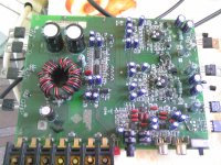
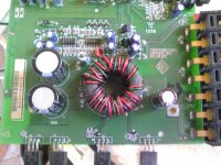
The TL494 has 21.01v on pin 8,11 and 12 any idea what could cause it to be so high? Rail voltage is + - 21.22v.
Most of the Rockford amplifiers use the output of the 15v regulator to boost the drive voltage for the power supply. If the regulator has failed, that could cause excessive voltage to be present on the 494.
The 494 is fed by two sources (on most Rockford amps). The initial input is from the remote terminal. After the switching power supply is up and running, the 15v regulator feeds the IC to boost the voltage and ensure that it remains steady. If the voltage isn't being driven too high by the regulator, it would almost certainly have to be from the remote input terminal. The problem is... the voltage on the remote terminal is monitored and if the voltage goes above about 16v, the amp should shut down.
If you can't find the fault, post the DC voltage on all pins of the LM339 and the 494 as well as the voltage on the B+ and remote terminals.
If you can't find the fault, post the DC voltage on all pins of the LM339 and the 494 as well as the voltage on the B+ and remote terminals.
Light blup in line for limiter.
IC#494
Pin 1: 2.18
Pin 2: 2.17
Pin 3: 3.43
Pin 4: .00
Pin 5: 1.45
Pin 6: 3.27
Pin 7: .00
Pin 8: 21.02
Pin 9: .15
Pin 10: .15
Pin 11: 21.02
Pin 12: 21.02
Pin 13: 4.82
Pin 14: 4.82
Pin 15: 4.83
Pin 16: .00
IC 339
Pin 1: 4.88
Pin 2: 4.88
Pin 3: 21.01
Pin 4: .52
Pin 5: 2.74
Pin 6: 4.66
Pin 7: 4.82
Pin 8: 4.82
Pin 9: 5.28
Pin 10: 4.82
Pin 11: 8.77
Pin 12: .00
Pin 13: 4.88
Pin 14: 21.64
Gnd to Remote 14.71
Gnd to B+ 14.71
I think that's normal for this amp. I don't have this schematic diagram but the 100a2 seems close and it takes the boost voltage from the rails instead of from the regulator. There are only a few amps that do this. The rest take the boost voltage from the regulators. Email me if you want a copy of the 100a2 diagram.
- Status
- Not open for further replies.

