Hi,
I have been looking at my DC heater circuit that uses a CRC from a transformer feed after full bridge rectification and can't understand why it only works when I 'cheat' with the implied resistance of the transformer being really low (110mOhm) . When I stick a meter across the filament supply with the valve out it measures crazy high at 110R
The transformer quotes 10.5V
Confused !!!?!?
Any ideas, it's a pretty simple circuit.
I can't seem to attach the file .psu?
Attachments

That's not the transformer resistance, but the rectifier, caps, and probably something else.When I stick a meter across the filament supply with the valve out it measures crazy high at 110R
Poke the transformer terminals directly. Power OFF!
Just tested the 10.5V transformer tap at 400 mOhms
The voltage is 10V - so can I assume 10V across the filament will logically have to be 3.25A at the resistance of the filament?
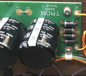
The voltages on the 211 are plate +1000V grid 0V Filament +50V and +60V (10V difference for the heater)
Yes this is two 47000 uF
I think the DC heater adaption was put on after the amp was considered about hum prone.
Thanks
The voltage is 10V - so can I assume 10V across the filament will logically have to be 3.25A at the resistance of the filament?
The voltages on the 211 are plate +1000V grid 0V Filament +50V and +60V (10V difference for the heater)
Yes this is two 47000 uF
I think the DC heater adaption was put on after the amp was considered about hum prone.
Thanks
Attachments
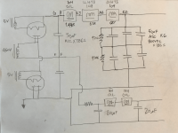
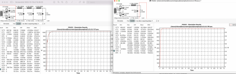
I have tried to model as best as I can the Power supply on another part of the amplifier - the B+ on the driver valve 6c45.
Once again the only way I make this work is to increase the supply conditions (in this case increase voltage( - I feel like I must be doing something wrong somewhere, as it does not seem to be close?
I have 138V and this correlates to about 18mV on the driver valve 6c45 (so I am assuming with ohms law this is about 7.6k load).
I have guessed some values, but have also made changes to see the sensitivity to changes and it just does not seem to correlate?
Attachments
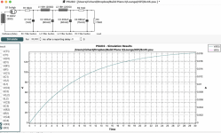
Uh, I think you are looking at the "A" scale and thinking "V".correlates to about 18mV
You get about 135Volts, after zero delay(?) and a 30 second(!) run.
The voltage is 138V output, BUT I had to put in 630V to make it work, the voltage after the valve is 500V. This comes from a voltage doubler, and I remodelled to include the lower cap on the voltage doubler that precedes the 10K, it still does not really make sense, I will keep trying and learning but the topology of how to model a single in line resistor is just guesswork hereUh, I think you are looking at the "A" scale and thinking "V".
You get about 135Volts, after zero delay(?) and a 30 second(!) run.
Your power supply (post #4) is rather non-conventional. Does it represent an actual working amplifier power supply that you have?
The 5U4 rectifier is a full wave, not half wave as shown in the schematic. The 10K resistor directly after the rectifier is rather large. With 0.018A flowing, the resistor drops 180V. C1 at 1nF is very small so that the power supply may act as choke input, further reducing the voltage.
Here is a summary of various power supply configurations and their voltages:
https://www.hammfg.com/electronics/transformers/rectifier
I suggest you delete the 10K resistor and change C1 to 5uF and see what PSUD gives you. And is your transformer actually 630V? That seems rather high for a 6C45. Or is it centre tapped to go along with the full wave rectifier? You should input the actual transformer specifications. If you are trying to model a working power supply, double check R1, R2, and C1.
Last edited:
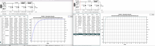
Then why do you have a 10k resistor FIRST? Larger than your load? Usually you want your filtering to be 5%-25% of the load resistance.BUT I had to put in 630V
And instead of way-huge L and C values, more filter stages gets cleaner cheaper.
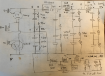
Ok - Sorry for not being clearer on my reason for using PSUD2. I have an amplifier and I am trying to better understand the configuration of the power supplies that are installed. The amplifier has a pair of 6c45 driver valves going through Lundhal 1660 interstage transformers into 211 output valves. The power supply for the B+ on the 211 comes from a voltage doubler using two 5u4GB valves. The transformer is labelled 0-450V. The measured out put at each rectifier is 1050 and 500V (or similar depending on the supply). I have a B+ for the 6c45 that comes from half of the doubler starting with 500V and then runs through the 10K resistor (I used an RC here and made the C1 insignificant I THINK) and through two oil filled chokes L1 and L2 both with a capacitor to earth c2, c3, then there is a bank of 4 capacitors to earth prior to the interstage transformer (again I tried to make the R part of the RC insignificant). Both valves and interstage transformers are fed from the single power supply so I made an assumption to put the R3 as the sum of interstage plus plate in parallel?
Anyway it's all good learning!
Thanks for the combined brain power 🙂
Anyway it's all good learning!
Thanks for the combined brain power 🙂
This is great - thanks. The 630V was put in the simulation to try and match the outcome of my actual amplifier at the 6C45 valve 139V with 1.6V cathode. The actual supply is supposedly 450V based upon the transformer labelling.Then why do you have a 10k resistor FIRST? Larger than your load? Usually you want your filtering to be 5%-25% of the load resistance.
And instead of way-huge L and C values, more filter stages gets cleaner cheaper.
View attachment 1064838
Part of my challenge is to learn as much as I can prior to lifting a VERY heavy amplifier off a shelf as a 2 man job to measure !!
Ok - so I have now concluded what the Power Supply circuit is in my amplifier, and I am looking for some expertise, as I am considering changing the Power supply caps from electrolytic to Film Oil (ASC X386S) based on popular opinion. The electrolytic caps are 20 years old, and having some exchange with another DIYer he suggested that a single CLC sounds better than multiple in a row CLCLCLC like I currently have. Your thoughts welcome on the topic of PS design, I have attempted as a layman to use the PDUD2 software to predict the ripple and response.
Attachments

- Home
- Amplifiers
- Power Supplies
- PSUD2 Question