I'm getting pretty close to completing my first high voltage(450V) tube amp but I am struggling with the PSU.
I have a 230:355V CT power transformer hooked up to a full bridge rectifier(CT not utilised) feeding into 1500uF of caps through a 10ohm for current limiting and then an RC filter that also drops the voltage to the 450V I need for my design.
The problem is that the transformer is giving me about 600V after the rectifier because I am not loading it much(only drawing about 5mA at the most, transformer secondary specced at 130mA). This isn't a huge issue for the tubes but the caps I am using won't survive that for long.
So far I have tried putting a 100V zener in series but they short instantly when I plug in the power because of the massive inrush current.
I am not really sure how to fix this besides loading the transformer more with power resistors or light bulbs or something. I was looking at maybe using a stabiliser tube instead of the zener but then I read that any capacitance over a few hundred nF would cause it to oscillate so I don't think that would work either...
Maybe I should just beef up the inrush resistor a bunch?
Thanks for any help 🙂
Last edited:
The orthodox way of solving such an issue is to use a choke-input filter: it will bring the voltage slightly below 500V, and has side benefits, like better regulation, better filtering, lower peak currents, better power factor.
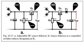
The iconoclast's way of solving the problem is to use a circuit like this one:
https://www.diyaudio.com/community/...f-converting-220v-to-110v.178606/post-2389035
It is a peculiar phase-control circuit, and can lower the input voltage to whatever level is required. It will generate current spikes, but no worse than with a capacitor input filter
Really that transformer is simply too high in voltage for the job, assuming a cap input rectifier. 500Vac gives you about 700Vdc in theory, and it is kinda silly to try to burn off hundreds of volts to get down to 450V. Could you reconfigure your amp design to work with 350Vdc instead (e.g. 250-0-250 two-diode rectifier)?
Last edited:
Typo in the OP, it's 230:355, giving ~500V after rectification theoretically 🙂Really that transformer is simply too high in voltage for the job, assuming a cap input rectifier. 500Vac gives you about 700Vdc in theory, and it is kinda silly to try to burn off hundreds of volts to get down to 450V. Could you reconfigure your amp design to work with 350Vdc instead (e.g. 250-0-250 two-diode rectifier)?
Not using a capacitive dropper here if that's what you mean, it's just wall -> transformer -> inrush resistor -> reservoir caps -> filter. I'll draw a sketch and post it.
I was also thinking of chokes but the ones I have seen used are real conkers at several Henry which there is no space for in the case nor my wallet 😂 took a quick look at that active circuit, seemed pretty cool but also not sure where I'd fit that. The case is basically way too small already and I don't feel like making a new one right now 😅The orthodox way of solving such an issue is to use a choke-input filter: it will bring the voltage slightly below 500V, and has side benefits, like better regulation, better filtering, lower peak currents, better power factor.
The iconoclast's way of solving the problem is to use a circuit like this one:
https://www.diyaudio.com/community/...f-converting-220v-to-110v.178606/post-2389035
It is a peculiar phase-control circuit, and can lower the input voltage to whatever level is required. It will generate current spikes, but no worse than with a capacitor input filter
Still pretty hot. Add a bucking transformer? Shaving 40V off the primary voltage would get you close...
You haven't told us what the rest of the amplifier looks like. Average current demand? Or did you mean the entire finished amplifier will only draw 5mA? If it's that small you could add a simple MOSFET follower (capacitor multiplier) to reduce the voltage, since it would burn away less than 1 Watt.
You haven't told us what the rest of the amplifier looks like. Average current demand? Or did you mean the entire finished amplifier will only draw 5mA? If it's that small you could add a simple MOSFET follower (capacitor multiplier) to reduce the voltage, since it would burn away less than 1 Watt.
Could we check what you have. Your PT is 230Vac input and 355-0-355Vac output? Your wall supply voltage is 230 Vac. You say you don’t use the center tap, meaning that your are putting 710Vac across the bridge rectifier? Is this correct? More details of your circuit power requirements and power supply would yield better advice.
The HT part will draw about 8-10mA(i also had that mixed up only looking at the draw from one side oops...). The schematic can be found in my 8136 amp idea thread here. It's a 12AX7 LTP going into SEPP 8136s OTL for 50ohm headphones. Something I cooked up mostly on my own as I had these tubes around 🙂Still pretty hot. Add a bucking transformer? Shaving 40V off the primary voltage would get you close...
You haven't told us what the rest of the amplifier looks like. Average current demand? Or did you mean the entire finished amplifier will only draw 5mA? If it's that small you could add a simple MOSFET follower (capacitor multiplier) to reduce the voltage, since it would burn away less than 1 Watt.
You mean like a buck converter? Don't really want to introduce switching noise...
Nope, it's 355V across the outside taps going into the rectifier. Center tap is not used. Should have just not mentioned it honestly.Could we check what you have. Your PT is 230Vac input and 355-0-355Vac output? Your wall supply voltage is 230 Vac. You say you don’t use the center tap, meaning that your are putting 710Vac across the bridge rectifier? Is this correct?
No, a buck transformer drops voltage continuously, no switching involved.You mean like a buck converter? Don't really want to introduce switching noise...
But if you only need 10mA then a capacitor multiplier or MOSFET follower would be easy and cheaper to implement.
Attachments
Nope, it's 355V across the outside taps going into the rectifier. Center tap is not used. Should have just not mentioned it honestly.
Is the 355v what you are reading with a meter and unloaded or is that the rated spec... 175-0-175v. If it is what you are reading unloaded then the spec would be lower like 160-0-160 loaded.
It's the rated spec, with a meter I've only probed the output which reads around 600V as stated I the OPIs the 355v what you are reading with a meter and unloaded or is that the rated spec... 175-0-175v. If it is what you are reading unloaded then the spec would be lower like 160-0-160 loaded.
Ah alright, how would I go about picking a suitable mosfet and potentiomer for a circuit like that then? Would be nice and small too which is a bonus but I am a bit concerned about the inrush exploding the mosfet like the zenersNo, a buck transformer drops voltage continuously, no switching involved.
But if you only need 10mA then a capacitor multiplier or MOSFET follower would be easy and cheaper to implement.
It's the rated spec, with a meter I've only probed the output which reads around 600V as stated I the OP
OK, so it's 175-0-175. For a headphone amp you have plenty of voltage using the CT and FW rectification for 12ax7 and 8136. 200v is plenty for either tube. You have plenty of voltage and can do some good decoupling and 2 stage filtering and won't need high voltage caps or a giant first filter or zener...
Last edited:
If I was to change the already built topology of the amp to something else then maybe that could work, but I have already built everything else and I'm not too keen on changing my entire design at this stage. Might as well throw the entire thing out at that pointOK, so it's 175-0-175. For a headphone amp you have plenty of voltage using the CT and FW rectification for 12ax7 and 8136. 200v is plenty for either tube. You have plenty of voltage and can do some good decoupling and 2 stage filtering and won't need high voltage caps or a giant first filter or zener...
OK. 355Vac =>
Bucking transformer: Something like this with sufficient voltage to ge you to 450 Vdc. (Described on Rod Elliotts website)

Or, I might try a much smaller input capacitor (say 8 mF, DC-Link or oil to handle the ripple current). Your first cap is pretty big.
Bucking transformer: Something like this with sufficient voltage to ge you to 450 Vdc. (Described on Rod Elliotts website)
Or, I might try a much smaller input capacitor (say 8 mF, DC-Link or oil to handle the ripple current). Your first cap is pretty big.
If I was to change the already built topology of the amp to something else then maybe that could work, but I have already built everything else and I'm not too keen on changing my entire design at this stage. Might as well throw the entire thing out at that point
Your PS is meant for a different class of amp if you don't use the CT or choke input. The 8136 has a plate max of 330v. Are you really going to put 450v on it?
Should have explained that the suggestion is the smaler cap and an R (or L if you could fit one) in front of your existing PS. Play around with PSUD2 (https://www.duncanamps.com/psud2/j if you know it to see what you could do in this regard. I get it that you want to do as little as possible on the PS you already built.Or, I might try a much smaller input capacitor (say 8 mF, DC-Link or oil to handle the ripple current). Your first cap is pretty big.
Last edited:
No, I'm putting 450/2=225V on it. The 8136s are in a push pull configuration and the 12AX7 gets it's voltage dropped by another zener.Your PS is meant for a different class of amp if you don't use the CT or choke input. The 8136 has a plate max of 330v. Are you really going to put 450v on it?
Smaller cap is probably not happening at this point as the case is built around it. A changing the 10ohm inrush resistor to something much larger sounds like the solution then as I don't think I can fit an inductor of more than a few mH anywhere.Should have explained that the suggestion is the smaler cap and an R (or L if you could fit one) in front of your existing PS. Play around with PSUD2 (https://www.duncanamps.com/psud2/j if you know it to see what you could do in this regard. I get it that you want to do as little as possible on the PS you already built.
So resistors before the transformer as well? Any benefit to them being there rather than after?Can this sketch solve your PSU problem?
You can use copper winding resistance in the secondary in addition to the added resistor to your advantage, if you added it to primary, it will work (maybe slight mismatching of impedance) and loss of power drawn.
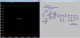
You don't need an actual pot, it just represents how you could set the voltage, you would use fixed resistors. Any 850V+ MOSFET should be fine, bigger the better (bolt to the chassis with suitable insulating hardware). Include a current-limit so the inrush cannot damage the MOSFET. Here you go, 600V in, about 450V out, limited to 60mA. Q2 can be any general purpse NPN. Easy peasy.Ah alright, how would I go about picking a suitable mosfet and potentiomer for a circuit like that then? Would be nice and small too which is a bonus but I am a bit concerned about the inrush exploding the mosfet like the zeners
Attachments
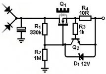

Oh cool, thank you! Is the cap behind the rectifier my 1500uF one? And if so would it be fine to move it to the other side of the MOSFET? The main reason that the 600V is an issue is that that cap would die pretty fast at that voltage 😅 (the caps in this amp are already specced for a good time not a long time but you know, don't need them to explode day one)You don't need an actual pot, it just represents how you could set the voltage, you would use fixed resistors. Any 850V+ MOSFET should be fine, bigger the better (bolt to the chassis with suitable insulating hardware). Include a current-limit so the inrush cannot damage the MOSFET. Here you go, 600V in, about 450V out, limited to 60mA. Q2 can be any general purpse NPN. Easy peasy.
- Home
- Amplifiers
- Tubes / Valves
- PSU struggles