I just bought an old (1965) Hewlit Packard 103AR.
100KC and 1MC sine outputs.
It's a transistor based unit.
http://i5.photobucket.com/albums/y177/Midiot/DSCN2342.jpg
http://i5.photobucket.com/albums/y177/Midiot/DSCN2343.jpg
http://i5.photobucket.com/albums/y177/Midiot/DSCN2344.jpg
It uses an outboard power supply (HP 724BR, or 725AR) which I do not have. In fact, I cannot find anything about the psu except that it is a battery backup type (for outage protection). An old HP catalog gives only these specs:
24v ( +2v )
500 ma
By looking at the 103AR's power input portion of the schematic, it seems to be negative 24 volts:
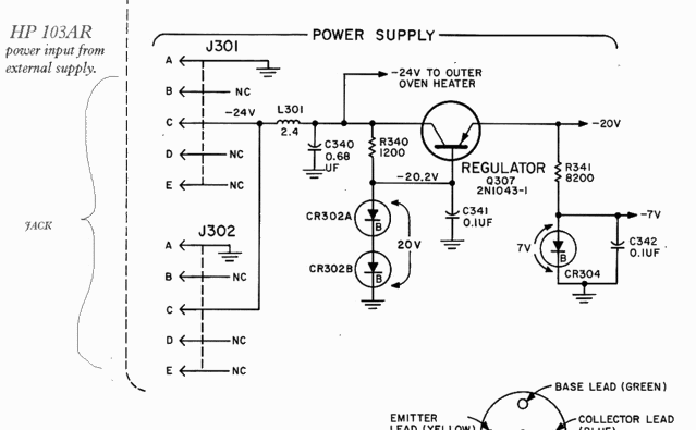
(there are two jacks, but only one is used. Ground is tied to case, -24v to circuit, I visually checked.)
I just want to do a "dead or alive" test. Do you think it's ok to use a properly set-up Lab PSU, @ -24 v...?
I have a LM7924 negative regulator, and I can whip up a 500 ma psu , for a more permenant solution.
...OR should this be -24 v rectified, but unregulated ...???
Thanks.
=RR=
100KC and 1MC sine outputs.
It's a transistor based unit.
http://i5.photobucket.com/albums/y177/Midiot/DSCN2342.jpg
http://i5.photobucket.com/albums/y177/Midiot/DSCN2343.jpg
http://i5.photobucket.com/albums/y177/Midiot/DSCN2344.jpg
It uses an outboard power supply (HP 724BR, or 725AR) which I do not have. In fact, I cannot find anything about the psu except that it is a battery backup type (for outage protection). An old HP catalog gives only these specs:
24v ( +2v )
500 ma
By looking at the 103AR's power input portion of the schematic, it seems to be negative 24 volts:
(there are two jacks, but only one is used. Ground is tied to case, -24v to circuit, I visually checked.)
I just want to do a "dead or alive" test. Do you think it's ok to use a properly set-up Lab PSU, @ -24 v...?
I have a LM7924 negative regulator, and I can whip up a 500 ma psu , for a more permenant solution.
...OR should this be -24 v rectified, but unregulated ...???
Thanks.
=RR=
Here is a zipped file of the HP 103AR manual/plus schematics.
It's several gif photos of the pages:
http://www.xertech.net/data/hp103ar.zip
=RR=
It's several gif photos of the pages:
http://www.xertech.net/data/hp103ar.zip
=RR=
if its isolated it won't matter. it will either be 20V or -20V depending on which terminal you call ground. I haven't read the manul, so doublecheck this.
I've never used a psu that was hooked-up for a negative supplied circuit.
From what you suggest, this just a matter of using a regulated or unregulated +24v psu, but attaching the power leads in reverse.
----------------------
Earth ground
Case ground
What about the earth ground to the unit I am powering ?
...because according to the pic/diagram I posted above, one leg of this psu will be tied to case ground, and when the oscillator unit is attached to another piece of gear, will get tied to earth ground. ( the bnc connectors are not isolated from case ).
=RR=
Pretend this uses a 24v regulator(7924):
(and other appropriate values/ xformer, etc.)
http://www.talkingelectronics.com/projects/ThePowerSupply/imagesP79/P79Fig33.gif
.....yes?
what about "isolation" ?
=RR=
(and other appropriate values/ xformer, etc.)
http://www.talkingelectronics.com/projects/ThePowerSupply/imagesP79/P79Fig33.gif
.....yes?
what about "isolation" ?
=RR=
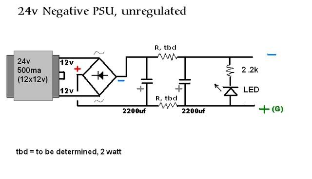
or Unregulated...
does this look good?
=RR=
EDIT:
I think I see what I've done here, It's a normal +24v psu......drawn upside down .
.
(I could probably come up with a diode regulated version too.)
does this look good?
=RR=
EDIT:
I think I see what I've done here, It's a normal +24v psu......drawn upside down
.(I could probably come up with a diode regulated version too.)
I don't have much practice building single psu's. I've built many dual psu's.
The resistors between the filter caps, should they be on both rails, or just on the neg (non-ground) rail ? (I'm so used to doing psu's symmetrically, that I'm not sure about this .
=FB=
Is there anybody out there that can tell me if I am even close to achieving a working psu....anyone?
The resistors between the filter caps, should they be on both rails, or just on the neg (non-ground) rail ? (I'm so used to doing psu's symmetrically, that I'm not sure about this .
=FB=
Is there anybody out there that can tell me if I am even close to achieving a working psu....anyone?
I just built this.
I made a few changes....snubbers, and a bleeder resistor because the caps were staying energized for about 30 seconds.
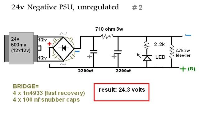
What do you think ?
(you obviously know what I think....typing, typing....)
=RR=
I made a few changes....snubbers, and a bleeder resistor because the caps were staying energized for about 30 seconds.
What do you think ?
(you obviously know what I think....typing, typing....)
=RR=
Thanks "theChris" for being the only brave responder.
I ordered a HP manual for the proper power supply, and hopefully it has schematics.
...because upon examining the oscillator's manual, it mentions that the power used to keep the oven going is 10 watts at initial warm-up stage, and 5 watts thereafter, which does not coincide with the 500 mA spec seen in an HP catalog....hmmmmm. I'll wait to see the schemo before powering the whole thing up. I don't want to damage that irreplaceable crystal.
Maybe the 500mA spec id when it's at idle, no load?
=RR=
there may be some examples in the chip amp forum. many toroid power transformers have dual secondararies instead of merely a center tapped secondary.
people just build two isolated, positive regulated power supplies and hook the outputs up in series.
This works due to the isolation.
as for your schematic, it looks ok. use a 1/2 resistor for the 2.2k.
keep in mind that the RMS input current to such a circuit is fairly high, i wouldn't run the circuit you list at 500mA output for instance.
Whether or not the original PSU contains a regulator (based on vintage and the presence of the regulator inside, I'd guess rather not), your easiest option is a 24V switchmode wall-wart or notebook supply. Over here, you can get those as "new old stock" from surplus dealers at ~$8. Outputs are floating wrt. earth anyway, so as theChris mentioned, you can connect +24 to pin A (GND) and 0 to pin C (-24) on your HP.
You may also be able to use an 18-19V switcher that you can open and trim the output up. Your HP should run fine on 21V regulated based on the circuit you show.
Alternatively, use an 18VAC transformer or wall-wart, slap on a bridge rectifier and 4700uF 35V cap and Bob's your uncle (I bet that's what HP did originally).
redrabbit said:... power used to keep the oven going is 10 watts at initial warm-up stage, and 5 watts thereafter, which does not coincide with the 500 mA spec seen in an HP catalog....
=RR= [/B]
It sure does, ma cher ... 24 V * 0.5 A = 12 Watts, that's all it needs. Your idea of using a 24V AC trafo and dropping the excess volts in a 700-something Ohms resistor will not work however because as you discovered in that spec, current draw will vary at least 2:1. In PSU design one normally tries to keep source resistance LOW ....
Anyway, trafos with 18VA are easily obtained; 18 * 1.4142 - 1.5 = 25.5 and that's what the doctor ordered.
That "UPS" option you mention was very likely a 24V lead acid battery (or 2 x 12V in series), so there's another option for you there. Just don't overcharge these! Lead-acid chargers for cycle use pump out too many volts for this application - you have to regulate the charger output at 27.2V (2x13.6V) in standby mode, that is, leaving the batteries connected on the charger at all times (assuming normal constant room temp - a version for wide temp range would have to modify the charger voltage based on temp).
12V 7AH sealed lead packs for standby use are quite popular for alarm systems and PBXes; a pair of these will run your HP for about a day given your specs.
- Status
- Not open for further replies.
- Home
- Amplifiers
- Power Supplies
- PSU for HP 103AR Quartz Oscillator ??