Hi
I’m going to replace the storage electrolytic capacitors in a 15 years-old valve amplifier power supply but I can’t find the original components, not even the exact same values. I’d be very grateful if you could help me before ordering.
The originals are made by F&T, one 100uF/500v and two 220uF/500v, solder-lug type (large vertical aluminium cans screwed to the PCB and connected to it by wires).
I’m planning to use JJ(Tesla) electrolytic capacitors (the black ones with red lettering), probably ordered from audiokit.it website. For the 100uF I’ll use a 100uF/500v snap-in type (it’s easy to drill in the PCB two holes spaced 14mm for the pins and connect them to the solder pads with a short wire).
For the 220uF I have a doubt. JJ makes a snap-in 200uF/500v cap and a solder-lug 250uF/500v cap, and I don’t know which one to order. I’ve searched the DIY forum and it seems that an increased capacitance in a power supply may sound better but the higher inrush can stress too much the psu components (aggravated because this psu uses a toroidal mains transformer). The total capacitance increment would be small (from 540 to 600uF), although at such high voltage (500v-rated, with a B+ voltage of 430v) the energy stored would increase much more.
What do you recommend to use in place of the old 220uF: the 200uF or the 250uF capacitor?
Thanks for your help
Best regards
Jose
i am assuming these are in parallel with each other AND this is a non high freq. switching power supply?
at 60 cycles there won't be any significant change in inrush per cycle or change in the reactance in the filter.
oh and by the way, 200 to 250 is pretty close to the tolerance of those cap values in the operating environment and manuacturing.
either 200 or 250 would be fine.
at 60 cycles there won't be any significant change in inrush per cycle or change in the reactance in the filter.
oh and by the way, 200 to 250 is pretty close to the tolerance of those cap values in the operating environment and manuacturing.
either 200 or 250 would be fine.
Hi, James
Yes, it is a linear psu and the three electrolytics caps are in parallel. The tolerance specified in the F&T caps is -10%/+30%. I'll order the JJ(Tesla) 250uF/500v ones. Thank you very much for your help
(BTW, in my country the mains is 230v/50Hz, although I guess it is of no importance regarding the doubt I posted)
Regards
Jose
Hi,
pin pitch for a snap in cap at 14mm (0.55inch) is unusual.
Check again.
Your total capcitance is 540uF. I would expect a total between 500uF and 600uF to perform as well as the original (in good condition).
I do not know how long your new caps have been stored before you plan to power up.
I would be tempted to condition them before fitting, rather than take the chance of a blow up at 500Vdc.
Hi
You're right, Andrew: the pin spacing of the snap-in types is 10 mm (however, in the solder-lug type the spacing is 15 mm).
Regarding the last paragraph of your post, I didn't take this problem into account. I guess that a new capacitor has no charge, so the first time I power the amplifier after solder the three new JJ caps, they will charge with a big inrush because the energy to be stored is very high (if I'm not wrong, that total 600uF multiplied by squared 500 Vdc). Could this blow the diodes D1-4 (1N4007 rated at 1A) or another component, or even the house wiring fuse?
What do you mean when you refer to a capacitor "conditioning" before fitting them in circuit? How can this to be done? Thank you for your help.
Regards
Jose
Hi,
conditioning capacitors to 500Vdc will be a risky business unless you are very organised and design out the dangers involved.
If you are unsure then steer clear. Better to be safe.
Instead you could power up using the light bulb trick to save complete disaster if something is seriously wrong.
I think the light bulb will need to be towards the top end for tube gear (normally 40W to 150W in series with the transformer primary).
replacing caps.
Spendorspain:
As from the info I got, Your amp. is a tube amp. with diode rectified, total over 500 uf filtering caps. Now you want to replacing these caps. due to they have been using over 15 yrs.
Before you want to do the replacement, you have to consider the size and the brand factory. For sure the capacitance must not less than original, and the withstand voltages are the main factor.
Brand name could affect the sound reproduction of the tube amp.
May be you can't find the org. brand, replacement must take into account. For Ideal, you may consider Mallory, Sprague, Ero, Elna, Rubicon, ------- etc.
If the capacitance you replaced is smaller than org. you will get fast sound, bigger will be slow.
In tube amp. design, pwr. cct. always employed PIE type, either single PIE or double PIE, choke PIE or resistor PIE, therefore even if you use capacitance as little as 40 uf X 3, it only affects the sound quality, humble is not affected by reducing of capacitance.


WE CONSIDER PRICE AND QUALITY
Spendorspain:
As from the info I got, Your amp. is a tube amp. with diode rectified, total over 500 uf filtering caps. Now you want to replacing these caps. due to they have been using over 15 yrs.
Before you want to do the replacement, you have to consider the size and the brand factory. For sure the capacitance must not less than original, and the withstand voltages are the main factor.
Brand name could affect the sound reproduction of the tube amp.
May be you can't find the org. brand, replacement must take into account. For Ideal, you may consider Mallory, Sprague, Ero, Elna, Rubicon, ------- etc.
If the capacitance you replaced is smaller than org. you will get fast sound, bigger will be slow.
In tube amp. design, pwr. cct. always employed PIE type, either single PIE or double PIE, choke PIE or resistor PIE, therefore even if you use capacitance as little as 40 uf X 3, it only affects the sound quality, humble is not affected by reducing of capacitance.
WE CONSIDER PRICE AND QUALITY
Re: replacing caps.
Or is that a fact?
now there's a strong opinion.mitwrong said:If the capacitance you replaced is smaller than org. you will get fast sound, bigger will be slow.
Or is that a fact?
Thank for your comments. Unfortunately, I haven't found the original F&T caps. I've searched in the most known suppliers in internet and I'm afraid that to find 500V-rated capacitors is not easy. It seems the JJ(Tesla) caps are good-sounding and not too expensive. I've also seen the ELNA High voltage Cerafines, but they are very expensive (Black Gates, of course, are even more expensive!!). So, I'll probably order the JJ 100uF and 250uF/500v caps from Audiokit.it or Partsconnexion. Do you believe that the use of the smaller 200uF could make the samplifier ound faster (that way the capacitance would be 500uF in total vs the 600uF or the original 540uF)?
And I have a doubt. AndrewT wrote: "Instead you could power up using the light bulb trick to save complete disaster if something is seriously wrong. I think the light bulb will need to be towards the top end for tube gear (normally 40W to 150W in series with the transformer primary)".
Could you explain a little more? Is it needed to wire a standard incandescent light bulb in series with the "live" wire that goes from the IEC AC input to the transformer (via a dpst rotary switch)? Could you draw a diagram of this "light bulb trick" to clarify the wiring? Thank you.
Regards
Jose
Mains light bulb tester
Hi,
You need:-
plug top
socket outlet
bulb holder
3 core cable
2 core cable
Connect all three cores at the plug top.
run 3 core to socket outlet
Connect neutral and earth at the socket outlet. Leaving live ready for next connection.
Connect 2core to bulb holder.
Run 2core from bulb holder to socket outlet.
bring the 2core live to the spare live on the 3core
and the bulb return to the live connection on the socket outlet.
Insulate everything or preferably fit the socket and bulb holder into a back box.
Place a mains bulb in the holder.
Leave the socket empty.
plug in and switch on.
The bulb should be unlit.
switch off.
plug a known good unit into the socket outlet.
switch on.
the bulb should flash briefly or not at all depending on the current draw of the good unit. The unit should operate normally if the bulb does not glow. If it glows the unit may not operate as intended. try fitting a bigger bulb so that it does not glow.
Remove the bulb from the holder and the unit should go off.
tester is working.
Go ahead and plug in your amp and switch on.
If the bulb glows strongly then decide if this is due to a fault in the amp or if the bulb is too small.
While the bulb is glowing there is a little voltage in the amplifier.
You can take measurements and possibly identify what is wrong. But all voltages will be way below operating levels.
Light Bulb Trick
Spendor, Andrew T
Light bulb trick is widely used for electrician, when they want to connect an unknown appliance ( good or bad ) situation, they always in series a light bulb with the AC line, thus can prevent the risk of fire, appliance damage, or blowing fuses.
This method I, myself highly appreciate and manipulate for all my new build amplifier. With this " Trick ", Ive been save a lot of components.
WE FOLLOW GOOD METHOD TO IMPROVE OURSELVES
Hi,
I now use the light bulb after all maintenance, as well as new build.
It only takes a moment to lift the adaptor off the shelf and plug in the unit.
I now use the light bulb after all maintenance, as well as new build.
It only takes a moment to lift the adaptor off the shelf and plug in the unit.
light bulb trick
Hi
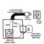
Thank you for your help. This post is to confirm if I have correctly understood the "light bulb trick". The wiring scheme is in the attached drawing. Is it correct?
The use of this trick would be this way: After soldering the new PSU capacitors (100+250+250uF at 500V), the first power-on of the amplifier wouldn't be with it connected to the wall socket, but connected to the AC socket outlet of the "light bulb trick" box. Thus, the caps would charge slowly at a reduced voltage because of the series-connected 100W bulb. If the bulb doesn´t glow, all is ok in the amplifier. After a while (perhaps a hour or so) connected this way, I would turn off the amp, and then (after 30 minutes or so) I would reconnect it, now directly to the AC wall socket: this time, with the caps not deeply uncharged (as they are when new), the inrush would be less severe. Is all the above correct? Please tell me if there is something wrong (a mistake here would be very dangerous).
Thanks again
Regards
Jose
Hi
Thank you for your help. This post is to confirm if I have correctly understood the "light bulb trick". The wiring scheme is in the attached drawing. Is it correct?
The use of this trick would be this way: After soldering the new PSU capacitors (100+250+250uF at 500V), the first power-on of the amplifier wouldn't be with it connected to the wall socket, but connected to the AC socket outlet of the "light bulb trick" box. Thus, the caps would charge slowly at a reduced voltage because of the series-connected 100W bulb. If the bulb doesn´t glow, all is ok in the amplifier. After a while (perhaps a hour or so) connected this way, I would turn off the amp, and then (after 30 minutes or so) I would reconnect it, now directly to the AC wall socket: this time, with the caps not deeply uncharged (as they are when new), the inrush would be less severe. Is all the above correct? Please tell me if there is something wrong (a mistake here would be very dangerous).
Thanks again
Regards
Jose
Attachments
Hi,
yes, the wiring is correct.
It will not take an hour, ten seconds will tell you if the initial bulb flash is going to extinguish.
Once you have established that there are no catastrophic wiring errors you may have to experiment with bulb wattage.
Start with low wattage and try higher watts until the amp appears to get at least 50% of full working voltage. A classAB solid state amp gets about 90% of working voltage through a 60W bulb.
Remember, since you are on valves to connect a dummy load!
I did a search for "capacitor conditioning," and this thread asked. So I'll ask again: How does one perform capacitor conditioning?
I have some large Philips 100000uF 30V caps that I would like to bring up to snuff.
I have some large Philips 100000uF 30V caps that I would like to bring up to snuff.
maybe "reforming" is your search parameter.How does one perform capacitor conditioning?
You need
a DC voltage supply preferably adjustable.
a couple of resistors 100k and 1M would do.
some croc clips on the ends of some leads.
a voltmeter that can read to ~40Vdc and down to Full scale ~200.0mVdc
Clip a lead from negative PSU to negative cap.
Clip a lead from positive PSU to 100k resistor.
Clip a lead from 100k resistor to positive cap.
Turn on the PSU
Read voltage drop across the 100k.
That tells you the charging current. It will be very low.
Come back every hour and recheck the cap voltage and the resistor Vdrop.
If you want to be all techy draw a graph of V against time.
Compare your different capacitors.
When the volts drop across the resistor becomes too low to measure try changing to the 1M resistor.
If you have sufficient leads and sufficient resistors you can reform any number of caps simultaneously from a single PSU.
AndrewT: Thanks for the thorough instructions! I was hoping you would weigh in, as you are always very knowledgeable. Indeed, 'reforming' is the key word on Google (although it doesn't seem to be discussed much on diyaudio....)
maybe "reforming" is your search
If you have sufficient leads and sufficient resistors you can reform any number of caps simultaneously from a single PSU.
I think use the word " recondition " is much suitable in this case.
The way Andrew T suggested is a good idea, if add in discharging the caps and do it in cycles would refresh the chemical of the caps more effciency. Usually I will use 10K resistor to perform this job, 100K or 1M may not fit enough to perform the charging.
😱😱😱
- Status
- Not open for further replies.
- Home
- Amplifiers
- Power Supplies
- psu capacitors replacement