Hi everyone, I have problem with this protection (k4700)
when i turn it on the ERORR led enlights and never goes off
but when i disconnect the lm324 from socket the delay circuit works just fine and after 6 second relay works
checked, no short circuit, and dc
also I used a symm. 12v power supply for it and didn't use itselfs ps
Thanks and sorry for my english
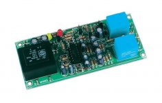
here is its picture i found
anybody? plz
when i turn it on the ERORR led enlights and never goes off
but when i disconnect the lm324 from socket the delay circuit works just fine and after 6 second relay works
checked, no short circuit, and dc
also I used a symm. 12v power supply for it and didn't use itselfs ps
Thanks and sorry for my english
here is its picture i found
anybody? plz
Attachments

You need to start by measuring voltages.
Measure with respect to ground (black meter lead on ground) what is the voltage on:
A1 output
A2 output
A3 output
A4 output
report back with the readings... we have to start somewhere 🙂
Measure with respect to ground (black meter lead on ground) what is the voltage on:
A1 output
A2 output
A3 output
A4 output
report back with the readings... we have to start somewhere 🙂
You need to start by measuring voltages.
Measure with respect to ground (black meter lead on ground) what is the voltage on:
A1 output
A2 output
A3 output
A4 output
report back with the readings... we have to start somewhere 🙂
tnx for respond to you
A1-A4 outputs are near 14 volts
is it normal?
That is not good. A1 and A2 outputs should be close to 0 volts.
If those outputs are near 14 volts, something is wrong.
If those outputs are near 14 volts, something is wrong.
That is not good. A1 and A2 outputs should be close to 0 volts.
If those outputs are near 14 volts, something is wrong.
sry I thik I was measured wrong somehow, I checked it again
A1 and A2 are very near zero (0.02)
and A3 and A4 near 3 and 3.1 is this measures normal?
No. Check that you have the proper power supply voltages on the LM324. +12 on pin 4 and -12 on pin 11. It must be a bipolar supply. +12, 0, -12. Common 0 volts should be connected at the junction of C12 and C13.
Disregard this. I wrote it before I saw your last post.
Disregard this. I wrote it before I saw your last post.
If the voltage on the output of A3 and A4 is negative 3.0, that should be okay. It should not be positive with respect to common ground.
Please check the orientation of the diodes on the outputs of A3 and A4 as well as diodes D5 and D6 on the input of A3 and A4.
Please check the orientation of the diodes on the outputs of A3 and A4 as well as diodes D5 and D6 on the input of A3 and A4.
sry I thik I was measured wrong somehow, I checked it again
A1 and A2 are very near zero (0.02)
and A3 and A4 near 3 and 3.1 is this measures normal?
I see a lot has happened...
A3 and A4 output should be a minus voltage that is equal to whatever the minus rail is. That is -V on the circuit.
A1 and A2 are OK at 0.02 v
Do you see D5 and D6 on the circuit ? Can you measure the DC voltage on each diode. You should have PLUS 0.6volts on D5 and MINUS 0.6 on D6.
power supply has +/- 12vdc and i conected 0 to outputs gnd
the voltages are negative
dc of diodes is exactly what you said
"PLUS 0.6volts on D5 and MINUS 0.6 on D6"
the voltages are negative
dc of diodes is exactly what you said
"PLUS 0.6volts on D5 and MINUS 0.6 on D6"
OK, that's good.
What are the voltages on C5 and C6 ? C5 should be lower than the voltage D5, and C6 should be more negative than the voltage on D6
Just measure what they actually are.
What are the voltages on C5 and C6 ? C5 should be lower than the voltage D5, and C6 should be more negative than the voltage on D6
Just measure what they actually are.
That last one I have the wrong way around, it should be more positive than the voltage on C6 but the actual voltages you measure should be near zero.
That last one I have the wrong way around, it should be more positive than the voltage on C6 but the actual voltages you measure should be near zero.
both caps are very near to zero, my multimeter does not have the sensitivity to measure it fine but its something like about 0.01
thanks a lot for helping
I've just about done for today but those readings are spot on.
As a recheck... confirm the outputs of A3 and A4 are still incorrect. They have to be close to the negative rail, so you should be seeing around -12 volts on both the outputs.
If they are not correct then check the diodes D7 and D8 are the right way round.
If you still find nothing amiss then we carry on fault finding by isolating D7 and D8 and checking each section in turn... tomorrow 🙂
I've just about done for today but those readings are spot on.
As a recheck... confirm the outputs of A3 and A4 are still incorrect. They have to be close to the negative rail, so you should be seeing around -12 volts on both the outputs.
If they are not correct then check the diodes D7 and D8 are the right way round.
If you still find nothing amiss then we carry on fault finding by isolating D7 and D8 and checking each section in turn... tomorrow 🙂
thanks a lot for your time
I checked again and you were right again A3 -9.99v and A4 -9.80v
I'm confused for wrong measures at first time
everything seems normal but stil error led lits amd relay does not work
everything seems normal but stil error led lits amd relay does not work
No problem 🙂 but we need to recheck a few things.
Is the power supply OK ? Without seeing what you have I can only assume its good. An oscilloscope would be useful here but we can try and work around that.
Lets try something different.
You measured around -10 volts on the output of A3 and A4. The LED will light when there is enough voltage difference between -V and the opamp output to turn on T1. There could be a few things going on (such as instability or AC present) and ideally an oscilloscope would be used to check this but we can get around that hopefully.
Make sure the inputs (PA LEFT and PA RIGHT) are NOT connected to anything. Leave them floating.
If you apply a short circuit across C5 and C6 does the circuit work normally with the LED remaining OFF.
No problem 🙂 but we need to recheck a few things.
Is the power supply OK ? Without seeing what you have I can only assume its good. An oscilloscope would be useful here but we can try and work around that.
Lets try something different.
You measured around -10 volts on the output of A3 and A4. The LED will light when there is enough voltage difference between -V and the opamp output to turn on T1. There could be a few things going on (such as instability or AC present) and ideally an oscilloscope would be used to check this but we can get around that hopefully.
Make sure the inputs (PA LEFT and PA RIGHT) are NOT connected to anything. Leave them floating.
If you apply a short circuit across C5 and C6 does the circuit work normally with the LED remaining OFF.
Hi again and Thanks to you
Inputs (PA L/R) are floating
and Error LED with short circuited c6 and c5 still on, I short circuited one of caps, then the other, and both of them, still LED is on
- Status
- Not open for further replies.
- Home
- Amplifiers
- Solid State
- Problem with velleman k4700 protection kit