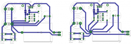
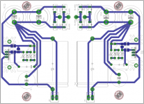
I am designing a simple pre-reg that will be feeding the K-Multiplier that resides directly on the pre-amp main board. The two will be housed in seperate enclosures. I am trying to determine if one of these layouts is better in terms of grounding than the other or are they both wrong. The actual star ground is not created until the two rails come together on the main board.
Attachments
Star grounding is good.
Especially in regards smoothing capacitor charging pulses.
I designed USB mixer and just laid the tracks as they came out of the schematic.
I had about 1 volt of hum on the output !!!
The problem turned out to be the power supply part of the design was not star grounded.
I proved this by removing the power supply to an external power supply on veroboard and the hum stopped.
I reworked the pcb with the smoothing capacitors ground taken right back to the star ground and it was very quiet.
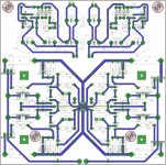
Zen Mod's is much closer.
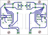
The input to the dual capacitors must be at the opposite end to the output from the dual capacitors.
The final output must be fed to that single cap on the right and the output must come from that final cap.
The input to the dual capacitors must be at the opposite end to the output from the dual capacitors.
The final output must be fed to that single cap on the right and the output must come from that final cap.
You need to "sort" the exit from the second capacitor.
In on one side and out on the other side.
The long spread of feeders from the first to second cap is wrong.
There are four capacitor pins that show the correct way.
In on one side and out on the other side.
The long spread of feeders from the first to second cap is wrong.
There are four capacitor pins that show the correct way.
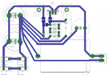
The electro at the bottom is not doing anything useful.
It has a common in/out. When located at the end of a a high impedance trace it's performance will be dominated by the trace impedance.
There is a film capacitor just above it.
It too has a long link back to the power supply. What does that film capacitor do? Will that long high impedance link interfere with what it is required to do?
The film cap is simply a bypass for the elco and should lower the overall Zo. Some say they heaer an improvement with such additions. I have seen them in some successful designs and had the caps to do it, so i went ahead and included them....in ignorance of their affect. I would be interested in seeing how you would lay it out, as i do not understand completely some of things you are referring to.
I don't know whether you will hear the difference.
Looking at the left side.
The small film cap between the Zeners and the last electro has a trace all the way back to the smoothing capacitors. This is wrong.
The cap is providing low impedance for the voltage reference feeding the series output device. It needs to be close to this reference loop. The -ve trace passes the Zeners. This is where it needs to connect. Delete the remainder of the trace back to the smoothing caps.
The final electro and it's bypass film go back to the smoothing caps. This is wrong.
The -ve trace passes the regulator instead of connecting to the regulator.
It needs to connect to the first supply point on that small electro. Delete the remainder of the trace to the smoothing caps.
Now your supply has TWO outputs, +ve and -ve. These TWO trace can run close coupled to the regulator.
The two traces between the smoothing caps can be close coupled.
The two traces from the rectifiers to the smoothing caps can be close coupled.
Finally the big film with the long traces cannot provide a low impedance for the client circuit.
It is too far away.
It should be moved to the client circuit and changed to a X7R ceramic.
If you keep it where it is you may have to add a resistance to damp any ringing due to the inductance of the long traces.
Buzz, I keep saying you again and again: Make a schematic layout in the Eagle, you will eliminate many mistakes that way.
These are not mistakes in the sense that the circuit will not work. THis is about appropriate routing of grounds traces to maxmize performance. Every iteration yousee will work. THe question is whether or not one layout will be quieter or perform better than another.Some would argue that to be truly serious, I should have a grounplane. Others say it is a non issue for audio, beyond DAC and RIAA stages.
Drawing a schematic eliminates mistakes, but does not guarentee proper layout. Most folks I have talked to scoff at the idea of auto layout. Euvl's F5X preamp will be built tonight, so i should be able to report something soon.
Drawing a schematic eliminates mistakes, but does not guarentee proper layout. Most folks I have talked to scoff at the idea of auto layout. Euvl's F5X preamp will be built tonight, so i should be able to report something soon.
Last edited:
Is this what you mean?The zener diode and parallel capacitor must be connected at output ground
The final electro and it's bypass film go back to the smoothing caps. This is wrong.
The -ve trace passes the regulator instead of connecting to the regulator.
It needs to connect to the first supply point on that small electro. Delete the remainder of the trace to the smoothing caps.
- Status
- Not open for further replies.
- Home
- Amplifiers
- Pass Labs
- Preamp grounding