With reference to the attached circuit diagram – I have had this pre-amp module lying around for some time (a long time – Purchased from Dick Smith Electronics way back in the 80’s when Dick Smith actually sold electronics components) and finally put it into service after replacing all the electronic caps - better to be safe than sorry.
The pre-amp has a little problem – high frequency noise (hiss)… The noise according to my oscilloscope is multiple frequency - can’t get the Scope to trigger on any particular timescale/frequency. I have now changed all the poly caps to MKTs, replaced all the carbon resistors with metal film and replaced the aged 2SC1000 transistors with BC549’s...
Replacing the capacitors in the tone control circuit did reduce the hiss by a small amount. I have added 10n ceramic caps across the power supply adjacent to both C12 and C13. I have insulated the Q1 & Q4 transistor base leads and installed ferrite beads to reduce external interference but this has made no difference. The volume pot loudness control tap cable between the switch and tap is shielded and grounded at one end only.
The signal inputs are shorted to ground.
My power source (as a temporary measure) is two 12V Alarm batteries in series because I suspected my 25VDC power supply was the culprit (Nope). The noise is appearing across the power supply provided via by the batteries. The pre-amp while connected to the amp is grounded via the shielded cables between the pre-amp output and amp module inputs.
The hiss volume does not increase when I turn the volume pot, it does however increase when I turn up the treble gain and is very pronounced at full gain. I am wondering if there is too much gain in the front end...
Open to suggestion...
Attachments
What are you driving this with? doesn't look suitable for RIAA phono moving magnet cartridge. Not enough gain, no RIAA curve.
If a high drive current source like a MP3 player, CD player, radio, drop the value of R2 R3 R24 R23. High value resistors hiss, and these values are suitble for a very high impedance source - like tape head?
If you're just using it as a tone control, then yes, dropping gain of first stage would help a lot. 23 db gain is fairly useless these days when most sources have an op amp driving the output jack to 2 vac level.
Last edited:
Is the hiss reduced with the volume pot on minimum ( thinking oscillating emitter follower ) . Alternatively try a 6.8pf capacitor across base and collector of Q2 and also Q5 .
Thanks for your responses. The pre-amp will be connected to a radio & CD player so no RIAA. I had dropped R2, R3, R24, R23 to 82K & 100k and also R11, R12, R32, R33 to 100k & 15k respectively. No change. Sorry should have said... As I stated originally hiss does not increase with volume pot only treble gain. Will try the capacitor suggestions and see how I go.
While c-b ceramic caps won't hurt anything in audio band, I would think if circuit was oscillating the scope would trigger on a wave. My 20 mhz scope did on 33078 op amp , at ~1 usec/div.
With radio or CD player source, you could skip the input gain stage and put c4 c17 cap input directly to the Vr2 pot wipers. Also cutting VR2 pot to 10 k may help
I you want to keep some gain,;leave the cap input as was and could change R4 R25 to 4.7k or 2.2k to decrease gain. Below that value you'd have to calculate power dissipation on Q1 Q4 to make sure it is not too high.
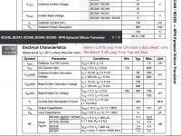
Also not all BC549 are created equal. Some (like the siemens datasheet I downloaded from datasheetcatalog) have no noise spec. Fairchild is showing 1.2 db noise on datasheet I downloaded last week from farnell.
Treble boosted does tend to accentuate hiss. I need to reactivate one of the salvage graphic equalizer boxes I've scored to check it out. My mixer has no tone controls.
Good experimenting. diy at its best.
With radio or CD player source, you could skip the input gain stage and put c4 c17 cap input directly to the Vr2 pot wipers. Also cutting VR2 pot to 10 k may help
I you want to keep some gain,;leave the cap input as was and could change R4 R25 to 4.7k or 2.2k to decrease gain. Below that value you'd have to calculate power dissipation on Q1 Q4 to make sure it is not too high.
Also not all BC549 are created equal. Some (like the siemens datasheet I downloaded from datasheetcatalog) have no noise spec. Fairchild is showing 1.2 db noise on datasheet I downloaded last week from farnell.
Treble boosted does tend to accentuate hiss. I need to reactivate one of the salvage graphic equalizer boxes I've scored to check it out. My mixer has no tone controls.
Good experimenting. diy at its best.
Last edited:
With respect you cant alter the gain of the first stage , it has none , its an emitter follower . It is there to buffer the tone control load from the input and they are prone to oscillation . To negate the possibility of oscillation put a 2.2K ohm resistor in series with the base of Q1 , ditto the right channel . The gain is determined by R17 and R18 left channel and R38 R39 right channel . To reduce the gain on both channels by 6dB reduce R17 and R38 to 9.1K ohm and increase R18 and R39 to 1.5K ohm .
If you keep the series combination of R17 R18 ( R38 R39 ) around 10K to not alter the current flow you can keep reducing the gain by altering this ratio but you will need to keep your eye on the polarity of C4 and C8 ( C17 C21 ) as it will reverse . Reducing the gain increases the likely hood of needing the 6.8pF caps as previously mentioned as you would be increasing the level of feedback and thus increasing the possibility of instability /oscillation .
If you keep the series combination of R17 R18 ( R38 R39 ) around 10K to not alter the current flow you can keep reducing the gain by altering this ratio but you will need to keep your eye on the polarity of C4 and C8 ( C17 C21 ) as it will reverse . Reducing the gain increases the likely hood of needing the 6.8pF caps as previously mentioned as you would be increasing the level of feedback and thus increasing the possibility of instability /oscillation .
Last edited:
diyralf and epicyclic posts are spot on point. This circuit is not, and cannot be made, HiFi -- no matter how much effort, cleverness, and parts you are willing to deploy -- it simply has too many shortcomings. If you are determined to experiment with it, I offer the following suggestions:
a) Put the original bias resistors back; the divide-by-ten changes you described will not help the noise issue. Reducing the impedance 10-fold, as you increase the current 10-fold, doesn't make appreciable difference. Think of being the original designer -- 1M and 820K resistors cost exactly the same as 100K and 82K resistors. Would YOU specify the former, if the latter gave a significant improvement?
b) Those impedance changes will alter the tone control ranges, as well as the volume, balance, and loudness contours. None of them will be 'correct'.
c) One of the greater shortcomings of this circuit (noise-wise) is that, of the 3 stages, 2 are emitter followers (giving 0 voltage gain, only current gain) -- the 2nd stage is providing THE ENTIRE 23dB of voltage gain! If you alter that overall gain, (as epicyclic suggests - changing R17,18,38,39), it may help the gain problem, but again will alter the range and accuracy of the tone controls (because they're within the NFB loop that controls overall gain).
d) This circuit reminds me of the ones by the fellers that spent their whole 40-year career designing tube gear, then had trouble adjusting to designing transistor gear that is current-based. The 250K volume and balance pots are kind of a giveaway -- those are tube-circuit values. It wasn't too unusual in the 70's and 80's to see designs like this: The guys that designed them were the age that I am now, and I promise, it's a hard adjustment.
e) You may need to consider how often you will need max-treble -- if that's the only time the hiss is objectionable -- because it probably can't be eliminated (without major overhaul).
f) If your sources are exclusively low impedance (3 to 5 K or less), you COULD bypass the 1st stage, but very likely would gain very little in noise floor. I don't recommend it.
g) There is a 3 resistor/1 capacitor way to bias the 1st and 3rd stages that may slightly reduce the noise, but you'll have to do some measuring (BC549 DC gain specs have a 7+:1 range) and arithmetic yourself -- PM me if you want - I'll try to help.
This is interesting from a technical standpoint, but like a lot of electronic things from 25 or 30 years ago, the gain is in the learning -- not so much the result.
Regards,
--Rick
Last edited:
Rick, Thanks for your response (and to others prior to you)...
The main reason I dropped the resistor values to the first stage was an attempt to reduce any Johnson noise they may have been adding...
Changing the original polypropylene capacitors to MKTs did make some difference but not a great deal.
Unfortunately the hiss is quite pronounced when the treble pot is in it's mid position and neglegible when fully anti-clockwise. It currently sounds like I am listening to an FM radio station that is slightly off-station. I will be using this pre-amp as part of a rudimentary system and it is built into a case (the reason I am hoping to save it) with an amp primarily to listen to FM Radio and the occasional CD while I am working...
I have now reduced the volume pot to 50k because, as you say a 250k volume pot is not necessary, I have left the balance pot alone...
Interestingly I have a pre-amp circuit design from 1976 that I built as a complete 40W amp kit in the late 70's that employs a very similar 3 transistor circuit with differing resistor (and capacitor) values and it was very quiet. The main difference with the 1976 circuit is that there is an 820k resistor between the emitter of stage 3 and the base of stage 2 (to provide feedback/stability?)...
Can forward a copy if you are interested...
Happy to take your assistance off-line...
Not sure how to PM you (new to this site) but will work that out...
The circuit has a very low quality and many problems. Don't use it for hifi.
This.
Op amp based circuits using low noise op amps and metal film resistors are very precise, low distortion, and low noise. There's no point in not using them.
I build tone controls using OPA2134, 5532, Dale SMF series resistors, Wima polypropylene caps, Bourns potentiometers. These circuits perform flawlessly and are virtually unimpeachable in every way. They are way, way better than virtually all tone controls used in any commercially built consumer grade equipment I've ever seen. And even with the fancy parts, you can build a board for less than $50. You can build a cheap knockoff (TL072, cheaper resistors, etc) for probably around $25 that would be almost as good. You could use just one op amp and skip the cascaded controls and get the parts count down even further, at the expense of precision, and you would still blow away the OP's circuit.
I think it would be very expensive to duplicate the performance of these op amp based tone controls with discrete components. It would have a high parts count, too.
Hi Mal,
Sorry for the extra trouble of a PM request, but I was worried my slow pace might bog down your thread otherwise -- I'm awfully slow. Now I gotta drop this in here 'cause I got all twisted up in my shorts trying to include a couple little JPEG's in the PM.
Your analysis is right on the money, with one small adjustment: C10 is bootstrapping Q2's collector load, which tries to make the gain infinite, up to Q2's beta * R13 -- at least at audio frequencies. This means that Q3's emitter divider ratio --
R18 / (R17 + R18)
sets the 23.9 dB overall gain by returning an opposite-phase signal (NFB) through C8. As long as both bass and treble pots are centered, the ends of each will be driven with equal but opposite signals.
There are four paths to improvement that I can think of:
A) a couple of BC549C's for the 2nd stages would probably have the best potential; note the almost 9 dB difference between the Typ value of the 549, and the Max value of the 547; BC550C slightly better still, and with a much better Vce safety margin for use in a circuit with 24V supply
B) reducing the surplus gain by lowering the bypass tap on Q2's emitter, R13/14, SEEMS like it oughta be a winner, but it'll take somebody with a higher pay-grade or math skills than mine -- or more Spice ability -- to say for sure
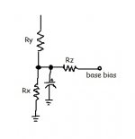
C) a slightly lower-noise bias technique would use a separate divider, noise-filtered with a small electrolytic; a little scribble below shows it; you'll want to measure the original base voltages to keep close to the same bias points, and set Rz to ~450K for Q1, and ~130K for Q2 (470K and 150 or 100K should be fine)
D) reducing the overall gain, as epicyclic mentioned, would quiet the hiss, too of course -- as long as you don't need the gain; try making R18 = 1500, and R17 = 8200, which will give about 16.2 dB, a reduction just shy of 8 dB, or try epicyclic's 1500, 9100 values if they're handier
Hope this helps enough. If not, maybe acquire LTSpice (which is free; or other simulation software) and cheaply try an even more extensive overhaul. But Fast Eddie D, diyralf, and other posters have some great points, too -- in the time you'll spend having all the fun you can have with this, you could probably design superior performance from scratch using newer parts and designs.
Note that the balance pot won't behave correctly with the lower impedance volume pot for a load.
Regards and good luck,
Rick
Sorry for the extra trouble of a PM request, but I was worried my slow pace might bog down your thread otherwise -- I'm awfully slow. Now I gotta drop this in here 'cause I got all twisted up in my shorts trying to include a couple little JPEG's in the PM.
Your analysis is right on the money, with one small adjustment: C10 is bootstrapping Q2's collector load, which tries to make the gain infinite, up to Q2's beta * R13 -- at least at audio frequencies. This means that Q3's emitter divider ratio --
R18 / (R17 + R18)
sets the 23.9 dB overall gain by returning an opposite-phase signal (NFB) through C8. As long as both bass and treble pots are centered, the ends of each will be driven with equal but opposite signals.
There are four paths to improvement that I can think of:
A) a couple of BC549C's for the 2nd stages would probably have the best potential; note the almost 9 dB difference between the Typ value of the 549, and the Max value of the 547; BC550C slightly better still, and with a much better Vce safety margin for use in a circuit with 24V supply
B) reducing the surplus gain by lowering the bypass tap on Q2's emitter, R13/14, SEEMS like it oughta be a winner, but it'll take somebody with a higher pay-grade or math skills than mine -- or more Spice ability -- to say for sure
C) a slightly lower-noise bias technique would use a separate divider, noise-filtered with a small electrolytic; a little scribble below shows it; you'll want to measure the original base voltages to keep close to the same bias points, and set Rz to ~450K for Q1, and ~130K for Q2 (470K and 150 or 100K should be fine)
D) reducing the overall gain, as epicyclic mentioned, would quiet the hiss, too of course -- as long as you don't need the gain; try making R18 = 1500, and R17 = 8200, which will give about 16.2 dB, a reduction just shy of 8 dB, or try epicyclic's 1500, 9100 values if they're handier
Hope this helps enough. If not, maybe acquire LTSpice (which is free; or other simulation software) and cheaply try an even more extensive overhaul. But Fast Eddie D, diyralf, and other posters have some great points, too -- in the time you'll spend having all the fun you can have with this, you could probably design superior performance from scratch using newer parts and designs.
Note that the balance pot won't behave correctly with the lower impedance volume pot for a load.
Regards and good luck,
Rick
Attachments
Hi Rick,
I lowered the gain as per Epicyclic's suggestion and the hiss at full volume and is almost indiscernible.
With regard to your option (C) I am not quite clear with regard to your suggestion...
This is what I think you are suggesting...
Existing Base Bias resistors are Rx & Ry (and these don't change in value).
What I need to do is add the resistor values you are suggesting in series with the base of each transistor Q2 & Q3 respectively together with say a 2u2 electro or tantalum capacitor...
I want to try this out for the sake of experimentation that is with the original gain resistors then with the 9k1 & 1k5 to see how the preamp performs......
Hi Mal,
Sorry -- I didn't explain that very well. Plus, I made a mistake in 'g)' of the 1st post.
Q3's operating point is set by Q2 -- it can't use or benefit from this technique.
Q1 and Q2 can, but it will take some fiddling. The idea is to measure the original voltage at each base, then install Rz and decrease Ry until the voltage at the base is back up to about where it was originally. Keep the signal connections, C3 and R10, as they are.
Note that this effort will likely only give a 1 or 2 dB improvement in noise floor. Substituting lower values for Rz would help more, of course. If you're willing to alter volume control slope and/or tone control range or slope, lowering them should be O.K. But you may need to increase C3 to maintain low frequency response.
The overall gain reduction remains the sharpest tool in the toolbox.
Hope this helps -- and that you're still having fun with it . . .
- Status
- Not open for further replies.
- Home
- Source & Line
- Analog Line Level
- Pre-Amp White Noise (Hiss)