Need a little help fixing this amplifier:
amplifier had all the power supply fets blown because of a shorted regulation choke. I fixed power supply by replacing blown fets and choke with another one i had from another ppi amplifier. Now the amplifier has high current in all the channels, about 10A per channel with no load connected to it. The amplifier has output though, but high current. I disabled all the outputs but one and measured VBE in each of the output transistors and measures .6V and base current is 4 mA. I have to measure quickly to protect output transistors from blowing up. If anyone has seen this problem or maybe I'm overlooking something I will appreciate any help.
Thanks
yes, I did but it still draws too much current, I also replaced the output card for the channel I'm working on but still didn't work. It act like the bias is all the way up, maybe has to do something with the voltages that go to the drivers, but I don't have a schematic to measure what voltages should be present.
If all the channels are high current that tells me that it might be the voltage feeding the drivers, I'm a little bit frustrated now.
I really appreciate your help Perry.
If all the channels are high current that tells me that it might be the voltage feeding the drivers, I'm a little bit frustrated now.
I really appreciate your help Perry.
Perry wants you to place pin shunts/jumpers to each channels bias shut down pins. If you install those pin jumpers the amp will effectively have all bias turned off to the outputs. Good idea perry...hope this helps some..😉
Thanks perry, going in the right direction. Putting the jumpers across the pins effectively turns the current down. Is there enough bias current with the shunts on.
Not for normal operation. Those are used to eliminate the bias current so that the amp can be serviced without having to worry about the output transistors overheating.
Are all of the thermistors under the board intact?
Are all of the thermistors under the board intact?
You're actually reading a 1.2k resistor in parallel with the thermistor.
Remove and check the bias transistor from at least one channel that you know to be drawing excessive current. Check for open junctions as well as leakage and shorted junctions. The bias transistors will likely be near the bias pots and will have a 1.2k resistor connected across its base and collector.
Remove and check the bias transistor from at least one channel that you know to be drawing excessive current. Check for open junctions as well as leakage and shorted junctions. The bias transistors will likely be near the bias pots and will have a 1.2k resistor connected across its base and collector.
Still going in the right direction. I replaced the bias transistor (mpsA06) for front channels and it worked. Both of them had base to emitter open, the question is why it happened, I wonder if when the regulation choke started going bad one of the rails went to high and damaged all of the bias transistors?
I don't know what caused it. I've never seen an amp with damaged bias transistors unless the outputs and drivers failed.
I don't know the factory bias specs. Does your amp have internal clamps or does the cover clamp the transistors to the heatsink?
All the channels work now. All of the bias transistors were open from emitter to collector. the cover does clamp the transistors. Thank you very much for your invaluable help Perry. You are the man!!
B.R
Rafael
B.R
Rafael
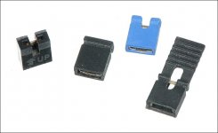
If you're going to work on these amps, you'll need to make clamps to allow you to clamp the transistors without the cover. If you want to make clamps, the attached photos shows the one that I find works best.
If y9ou won't likely work on any others, you'll have to set the bias by clamping the transistors for one channel the best you can and then set the bias. I'd set it to about 0.001v across the emitter resistors. You'd then install the shunt for that channel and do the same for all other channels. After setting the bias and powering the amp down, you'll remove the shunts and install the cover.
If y9ou won't likely work on any others, you'll have to set the bias by clamping the transistors for one channel the best you can and then set the bias. I'd set it to about 0.001v across the emitter resistors. You'd then install the shunt for that channel and do the same for all other channels. After setting the bias and powering the amp down, you'll remove the shunts and install the cover.
Attachments
- Status
- Not open for further replies.
- Home
- General Interest
- Car Audio
- PPI PC4100