I'm building a set of Unity horns (1 compression tweeter and 4 midrange drivers, time aligned, in a constant directivity horn). The horn goes from 300hz up, and will have a sensitivity of 105-110 db. I was thinking of a little pp based on 6ck4 output tubes. I have 30 watt pp on my main system now (box speakers) and like it. But I wondered if one might get noticible pp crossover
distortion effects at the very high efficiency of the Unity. I'll probably biamp the horn and use line level crossovers. My alternative is to make some little SE amps. I tend to like a clean neutral presentation, so I'd want a pretty clean SE if I go that way. Obviously, I don't need much power or bass out of these guys.
Sheldon
Class A PP has no crossover distortion. Neither does class AB. Heck, class B barely does, with tubes. Nil with NFB for sure. But whaddya need 110 + 10*log(30) = 124dB of audio for anyways? SE 12AU7 would be fine with that efficiency...
Tim
Tim
Sch3mat1c said:SE 12AU7 would be fine with that efficiency...
Oh boy! I sense a new thread..."The Ultimate SE 12AU7 Amp" 😎
Sch3mat1c said:Class A PP has no crossover distortion. Neither does class AB. Heck, class B barely does, with tubes. Nil with NFB for sure. But whaddya need 110 + 10*log(30) = 124dB of audio for anyways? SE 12AU7 would be fine with that efficiency...
Tim
I thought that the crossover distortion in class A was nil too. In talking to Jack at Electraprint, though, he thought it might be noticable with the very high efficiency. He wasn't referring to crossover distortion in the tubes, but in the loading/unloading of the transformer. The amp I was thinking of would put out about 5watts. Could try something like a 12au7, or for a little more, a 12b4 SE?
Sheldon
I thought that the crossover distortion in class A was nil too. In talking to Jack at Electraprint, though, he thought it might be noticable with the very high efficiency. He wasn't referring to crossover distortion in the tubes, but in the loading/unloading of the transformer. The amp I was thinking of would put out about 5watts. Could try something like a 12au7, or for a little more, a 12b4 SE?
There is crossover distortion at very low levels because the field in the core collapses and the magnetization curve is very curvey at low inductance. Single-ended output transformers are biased into the more linear regions of the magnetization curve by the gap and the DC inductance from the B+. Lots of feedback can make a sine wave look good, and push-pull can cancel even order distortion in a sine wave, but neither does much good for a music signal.
With horns, a well-designed single-ended triode amplifier almost always sounds better than a push-pull amp with feedback.
This is an easy to build and very good sounding amp:
http://www.diyaudio.com/forums/showthread.php?s=&threadid=30209&highlight=
Here's a photo of my own version:
http://www.diyaudio.com/forums/showthread.php?postid=464287#post464287
John
SE is only linear by the matter of travelling a narrow width along an exceedingly nonlinear curve. For an example, let y = x^3/2 and take a point at say, x = 3 +/- 1 (2 to 4). y then goes, around a center of 5.196, to 2.828 in the negative and 8 in the positive, for a difference of 5.196 +2.804 and -2.368. The difference of differences (bleh, English!) there manifests itself as a slight rise in DC current draw and even harmonics, in this case about 0.8% THD. Not bad for a crude SWAG of a mathematical approximation to reality (3 +/-1 (the +/- variation is equivalent to AC swing) would be a triode at maybe quarter of maximum power output, and the distortion isn't far off either.
But anyways ... if you go the whole length of the curve, from x = 0 to 6, instead of 2 to 4, you get a far greater nonlinearity.
So SE is more linear? No, this just says that amplifiers are more linear when they can handle signals much, much larger than what you use them for. 1W coming out of a 3W 6BQ5 amp isn't going to hold a candle to 1W coming out of a sextet KT90 200W behemoth.
Now... iron responds in much the same way, yes. Only in this case we compare zero-centered signals (because PP has the DC currents cancel) to biased signals (for your mathematical curiosity, yes the derivation is different because you need to find odd order harmonics in the above function!). This looks worse, but in reality it's never above 0.02% THD for standard OPT iron. You can hear maybe 1%.
Tim
P.S. Hrm. Symmetrical swing about zero, into a three-halves power equation? Eh... better ignore the imaginary numbers there for convienience. 😉
Sch3matIc, I have to disagree with your statement that class AB amps do not have crossover distortion.
I have just this week created a SwircherCAD model of the final stages of th STC 807 75 Watt class AB2 amp from the circuit in the STC 807 data sheet. See attachment.
If you run this model for a few cycles of the 1KHz input and then plot the output waveform together with the anode currents of the output tubes you can clearly see a "kinks" in the output sine wave at exactly the points where the tube currents drop to zero (This really stands out if you are used to looking at clean waves)
If you plot the signals on the 807 grids you see no such kinks, so I conclude this is purely cross over distortion in the output.
In that model I have disconnected the feed back path. Connecting it seems to be able to fix the distortion but playing with variuous feed back ratios I have seen terrible bursts of ringing in the output again coincident with the points of anode current hitting zero. I think we should not be suprised at the inductance of the output transformer doing this.
Also I noticed that applying feedback causes a very messy output signal when driven a little bit into clipping. With no feedback a little overdrive is a lot cleaner.
So whats wrong with my model ?. If it is reasonable I conclude class AB does have crossover distortion.
I also seem to have learned a few things about feedback along the way and now start to realize why many people consider it evil.
Notes on my model:
1) I'm new to tube designs and spice so this could be nonsense
2) My layout is nothing like the STC circuit or any other PP drawing I've seen but I hope it is basically correct.
2) SwicherCAD is a free download from Linear Technology so please someone try this as well. In this case some feedback would be welcome 🙂
3) I used the tube models from duncanamps.
4) I hope one day I can stop simulating and start building.
heater said:See attachment.
I'm a lookin but not a see-in' 😉
If you run this model for a few cycles of the 1KHz input and then plot the output waveform together with the anode currents of the output tubes you can clearly see a "kinks" in the output sine wave at exactly the points where the tube currents drop to zero (This really stands out if you are used to looking at clean waves)
What's the bias at? Is transconductance at this current equal to half that at high current (peak) levels? (If small signal (class A) transconductance is lower than the average value of it at large signals, 3rd harmonics reverse from positive to negative, causing the crossover distortion.) How about the OPT model, does it simulate the initial permeability of the OPT?
In that model I have disconnected the feed back path. Connecting it seems to be able to fix the distortion but playing with variuous feed back ratios I have seen terrible bursts of ringing in the output again coincident with the points of anode current hitting zero.
Odd. Plate current doesn't hit zero for one.
 (A tube can cut off quite nicely, but there will always be a few electrons leaking through to the plate. Especially at high peak voltages when the opposing tube drives the load. It also cuts off slowly because transconductance drops similarly smoothly, making it hard to excite parasitics. 😕 )
Does the OPT simulation model leakage inductance between the two halves of the primary? Primary to secondary? Any other intentional or unintentional parasitic circuits present?
Tim
So one vote for PP and one for SE. May have to build both and see. One question regarding Jselm's amp. Since the driver tube and output tube are are working in different directions with respect to the plate curves, one might some cancellation of the non-linearities? I suppose that with good models one could set conditions or select tubes such that this effect is optimized. I think John Broskie gave some examples in the Tcad journal of this technique.
Thanks,
Sheldon
Edit: Here's the reference noted above:
http://www.tubecad.com/articles_2001/Inv_Dist_Cancellation/index.html
Might be interesting to play with, especially as efficiency is not an issue for my app.
Thanks,
Sheldon
Edit: Here's the reference noted above:
http://www.tubecad.com/articles_2001/Inv_Dist_Cancellation/index.html
Might be interesting to play with, especially as efficiency is not an issue for my app.
Sorry Sch3mat1c here is the STC 807 spice file.
Seems when one hits "preview Reply" the attach file dialogue box cleared, anyway ".asc" is not an allowed file type. You will have to save the attachment as STC_807.asc to get it into SwitcherCAD.
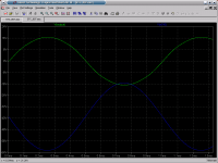
This simulation shows a 17v peak to peak output with clearly visibe kinks at +/-10volts. Just when one or other tube anode current goes to zero (Acually -450uA)
Yes the OPT model is as simple as can be (I copied it from the EL34 PP amp on Duncanamps) but I don't see that as contributing to those kinks.
Perhaps "cross over distortion" is not quite the correct term here as it is not happening at the zero crossing of the output signal but rather as we move out of class A operation.
So, anyone know if this normal and/or how to fix it ?
Seems when one hits "preview Reply" the attach file dialogue box cleared, anyway ".asc" is not an allowed file type. You will have to save the attachment as STC_807.asc to get it into SwitcherCAD.
This simulation shows a 17v peak to peak output with clearly visibe kinks at +/-10volts. Just when one or other tube anode current goes to zero (Acually -450uA)
Yes the OPT model is as simple as can be (I copied it from the EL34 PP amp on Duncanamps) but I don't see that as contributing to those kinks.
Perhaps "cross over distortion" is not quite the correct term here as it is not happening at the zero crossing of the output signal but rather as we move out of class A operation.
So, anyone know if this normal and/or how to fix it ?
Attachments
I don't have Spice/CAD anything. 🙁
That the current is going even to zero, let alone negative, especially at *higher* plate voltages, smacks of a bad tube model.
(Very rarely, secondary emission can cause negative screen current in some transmitter tetrodes. Low power tetrodes like type 42 or beam tetrodes like 6V6 have regions of negative plate *resistance* (meaning plate current drops as voltage rises), but still no negative screen current. Pentodes cannot have either characteristic, by design. At any rate, I doubt your model would be programmed to represent secondary emission anyway.)
No matter what Greggggggggeek says, 😉 simulation is for educational purposes only and if you aren't using accurate models or using them right, can be quite far from reality indeed.
Tim
The STC 807 amp, is that the one with a pair of 807´s driven by 6SN7 cathode followers?
I suspect that the kinks may be the result of the sudden increase of current through the cathode followers, ie when the grids starts to draw current the driver tubes "sags " bit. Just my 0,02 bucks
I suspect that the kinks may be the result of the sudden increase of current through the cathode followers, ie when the grids starts to draw current the driver tubes "sags " bit. Just my 0,02 bucks
SE of course!
There are plenty of theoretical arguments that PP is "cleaner and more accurate" than SE. I understand the arguments perfectly well, and intuitively they make perfect sense. Unfortunately, the conclusion that we should expect SE to sound "dirtier and less accurate" than PP just doesn't play out in my experience. In fact I might argue that SE is more accurate according to my ears since it brings more of the live experience into my home. [I've heard people say they like the laser etched clarity of PP, but live music has never sounded laser etched to me. ]
]
Anyway, you can build a really simple SE amp for cheap using a single 6EM7 per channel. It's pretty hard to make a bad sounding amp with these things as long as you're not asking for more power than it can deliver (something like 1 watt, which is several times what you need for Unity horns.)
Gary Kaufman has design you can build from parts you probably have in your junk box.
http://www.the-planet.org/6EM7.html
Buy, beg or borrow some half decent output transformers and I promise you'll be hooked.
-- Dave
Sheldon said:I tend to like a clean neutral presentation, so I'd want a pretty clean SE if I go that way.
There are plenty of theoretical arguments that PP is "cleaner and more accurate" than SE. I understand the arguments perfectly well, and intuitively they make perfect sense. Unfortunately, the conclusion that we should expect SE to sound "dirtier and less accurate" than PP just doesn't play out in my experience. In fact I might argue that SE is more accurate according to my ears since it brings more of the live experience into my home. [I've heard people say they like the laser etched clarity of PP, but live music has never sounded laser etched to me.
]Anyway, you can build a really simple SE amp for cheap using a single 6EM7 per channel. It's pretty hard to make a bad sounding amp with these things as long as you're not asking for more power than it can deliver (something like 1 watt, which is several times what you need for Unity horns.)
Gary Kaufman has design you can build from parts you probably have in your junk box.
http://www.the-planet.org/6EM7.html
Buy, beg or borrow some half decent output transformers and I promise you'll be hooked.
-- Dave
Re: SE of course!
Thanks,
Yeah, I'm thinking I might go with that or something along those lines. I'll check out the tube specs. With some part value changes, could probably even use tubes I have.
Sheldon
Dave Cigna said:
There are plenty of theoretical arguments that PP is "cleaner and more accurate" than SE. I understand the arguments perfectly well, and intuitively they make perfect sense. Unfortunately, the conclusion that we should expect SE to sound "dirtier and less accurate" than PP just doesn't play out in my experience. In fact I might argue that SE is more accurate according to my ears since it brings more of the live experience into my home. [I've heard people say they like the laser etched clarity of PP, but live music has never sounded laser etched to me.
Anyway, you can build a really simple SE amp for cheap using a single 6EM7 per channel. It's pretty hard to make a bad sounding amp with these things as long as you're not asking for more power than it can deliver (something like 1 watt, which is several times what you need for Unity horns.)
Gary Kaufman has design you can build from parts you probably have in your junk box.
http://www.the-planet.org/6EM7.html
Buy, beg or borrow some half decent output transformers and I promise you'll be hooked.
-- Dave
Thanks,
Yeah, I'm thinking I might go with that or something along those lines. I'll check out the tube specs. With some part value changes, could probably even use tubes I have.
Sheldon
Hi,
Recorded music is hardly ever recorded live and even hardly ever from the position the listener is normally sitting/standing.
To my mind a good amplifier should faithfully amplify what it's being fed. Therefore it shouldn't "sound" like anything at all.
How anyone goes about that, P-P or SE is really not that important.
I just have a very hard time imagening a SE amp driving both inefficient speakers and difficult loads.
Granted, modern speaker design needs a serious amount of rethinking...But that's another story.
Cheers,😉
[I've heard people say they like the laser etched clarity of PP, but live music has never sounded laser etched to me. ]
Recorded music is hardly ever recorded live and even hardly ever from the position the listener is normally sitting/standing.
To my mind a good amplifier should faithfully amplify what it's being fed. Therefore it shouldn't "sound" like anything at all.
How anyone goes about that, P-P or SE is really not that important.
I just have a very hard time imagening a SE amp driving both inefficient speakers and difficult loads.
Granted, modern speaker design needs a serious amount of rethinking...But that's another story.
Cheers,😉
Yes, sch3martc, I would not want to put to much faith in simulations and I feel less confident about the tube models. However just now I don't have any tubes to test reality with 🙁 and at my stage of tube amp education I'd just like to get a feel for operating points and such.
I recommend everyone here to download the free SwitchedCad spice program from Linear Technology, http://www.linear.com/designtools/softwareRegistration.jsp and follow the instructions on duncanamps site, if only as a scratch pad for kicking aroud ideas and, well, fun.
Fuling, yes that is the very same amp with 6SN7 cathode followers. But my grids are never going positive and the grid currents are small microamp range. The voltage signal on those grids looks just fine. See attachment. The lower trace is a grid and the upper is the OPT output (across an 8 ohm resistor). See the kinks.
So like the Sheldon I still don't know whether to go SE or PP. My gut feeling does not help as on the one hand I love symmetry (PP) on the other I love simplicity (SE). So it looks like the only thing to do is start lashing up one of each !
Attachments
This is a pretty easy to answer question...
With a high efficiency horn system your greatest enemy is noise floor and hum.
IF you are very careful and take lots of extra effort to make your
SE amp *very* quiet - which means extra effort and $$ in the power supply and with the filaments then you might be ok.
If you don't have the experience and test gear to see what is going on, then PP is almost always easier to make a quiet amp.
In the case of an SE amp for your horns, build one with what seems like *excess power* capability - so that you are reasonably certain to be running in a reasonably linear and low distortion portion of the curve. So if you need 3 watts, build a 5-10 watt amp. Like a 300B SE or one of the higher power versions thereof... paralelled tubes are an option with some benefits.
None of them will do well with feedback of the loop type, imho.
The ultimate quality will depend on your iron and your circuit linearity.
Anything *BUT* a triode is a bad idea, imho.
Make sure you do not couple your amp down to bass freqs - build the amp for the purpose. Keep the LF out of the iron.
Class A2 always sounds better to me than A1.
There is *always* xover distortion in AB. Xover distortion is merely gain variation due to non-linearity at the point where one device is no longer on the linear portion of its curve so the gains no longer sum as they do when they are in the linear portion. Nothing exotic about it.
For horns, Class A.
Then you can decide on xfmr coupling, SE or diff input stages, etc.
and of course "parafeed" output stage or not...
_-_-bear
bear said:This is a pretty easy to answer question...
With a high efficiency horn system your greatest enemy is noise floor and hum.
IF you are very careful and take lots of extra effort to make your
SE amp *very* quiet - which means extra effort and $$ in the power supply and with the filaments then you might be ok.
If you don't have the experience and test gear to see what is going on, then PP is almost always easier to make a quiet amp.
In the case of an SE amp for your horns, build one with what seems like *excess power* capability - so that you are reasonably certain to be running in a reasonably linear and low distortion portion of the curve. So if you need 3 watts, build a 5-10 watt amp. Like a 300B SE or one of the higher power versions thereof... paralelled tubes are an option with some benefits.
None of them will do well with feedback of the loop type, imho.
The ultimate quality will depend on your iron and your circuit linearity.
Anything *BUT* a triode is a bad idea, imho.
Make sure you do not couple your amp down to bass freqs - build the amp for the purpose. Keep the LF out of the iron.
Class A2 always sounds better to me than A1.
There is *always* xover distortion in AB. Xover distortion is merely gain variation due to non-linearity at the point where one device is no longer on the linear portion of its curve so the gains no longer sum as they do when they are in the linear portion. Nothing exotic about it.
For horns, Class A.
Then you can decide on xfmr coupling, SE or diff input stages, etc.
and of course "parafeed" output stage or not...
_-_-bear
Thanks,
Yes, I'm thinking along those lines. I'm definitely collectionginformation on good power supply design, as well as noise cancellation techniques. The idea of intentional distortion cancelling is appealing too. And part of this (a big part) is the opportunity to learn and experiment a bit. But that's most productive with a good starting point. I do plan to leave the LF out of the iron, as I will for sure use a line level crossover from the horn (300hz) down. I'm leaning to biamping the horn itself. I'm also leaning toward incorporating the crossovers directly into each amp chassis, along with buffers. It may take me a little to cook up a design, and learn how to make legible schematics, but I'll post it here when I do. I will probably have iron wound specifically for the application, which should mean improved linearity in the target region, no?
Regarding iron, anyone with thoughts on the possibility of OPT, especially versions without a big ol' coupling cap at the output (which would mean pp)? Or maybe the coupling cap would be more linear than any transformer? If I went that way, I'd like to avoid paralleling a bunch of tubes if I can. I haven't been able to find much there. Since the horn eff. should approach 110 db, I should only need a couple of watts to have plenty of headroom for non-earsplitting listening levels. The tweeter shouldn't require much power (TAD 2001) and I can also wire the mid's in series, so that I would have a nominal impedence of 32 ohms for them. That should make it easier, no?
sheldon
Sheldon said:[BRegarding iron, anyone with thoughts on the possibility of OPT, sheldon [/B]
Sorry if I had people confused here. I meant to say OTL.
Sheldon
- Status
- Not open for further replies.
- Home
- Amplifiers
- Tubes / Valves
- PP or SE for Horns?