Hi guys,
I don't usually do SS stuff but the need has arisen for output buffer (to replace OPT and to be coupled to triode gain stage, no feedback loop in the amplifier so capacitor coupling at input and output). Goals are:
- simple (few, easy to find parts)
- somewhere in the neighbourhood of 20-30W out into 8R
- negliible load on VAS (so it can drive multiple output stages in parallel)
- be idiot proof
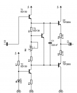
Below is the easiest schematic I could come up with. CCS LED is power indicator and is shared among all output stages (drawn here for the sake of completeness only).
Any comments or alternative suggestions would be greatly appreciated.
Few questions:
1: Transistor choices, sane or not ?
2: T1 and T2 shouldn't be on same heatsink as other three transistors, correct ?
3: Output protection diodes (to supply rails), needed or not ?
4: Output emitter resistors, how to size them resistance-wise ?
5: Any ideas for powerup "thump" elimination ?
I don't usually do SS stuff but the need has arisen for output buffer (to replace OPT and to be coupled to triode gain stage, no feedback loop in the amplifier so capacitor coupling at input and output). Goals are:
- simple (few, easy to find parts)
- somewhere in the neighbourhood of 20-30W out into 8R
- negliible load on VAS (so it can drive multiple output stages in parallel)
- be idiot proof
Below is the easiest schematic I could come up with. CCS LED is power indicator and is shared among all output stages (drawn here for the sake of completeness only).
Any comments or alternative suggestions would be greatly appreciated.
Few questions:
1: Transistor choices, sane or not ?
2: T1 and T2 shouldn't be on same heatsink as other three transistors, correct ?
3: Output protection diodes (to supply rails), needed or not ?
4: Output emitter resistors, how to size them resistance-wise ?
5: Any ideas for powerup "thump" elimination ?
Attachments
I do not know enough to comment on your posted design, so here are a couple of alternatives:
FirstWatt / Nelson Pass F4 is an output buffer
Wim de Hann has some projects with tube + buffer at Wim's DIY Audio Projects
Example 1: Mugen hybrid amplifier
Circuit: http://www.wimdehaan.nl/images/mugencircuit.jpg
Example 2: Nishiki hybrid amplifier
Circuit (on page 10): http://www.wimdehaan.nl/downloads/technicalmanualnishiki41.pdf
Thanks for the links. This author went with tubey follower (I want it simple so it will be suitable project for beginners, cathode follower is waste of one tube in this case). It appears diodes (question 3) are a good idea afterall 🙂
They did remind me of something I forgot: driver transistors - unless I want to cook T1 and T2 they won't be able to supply enough current for worst case beta of output devices, correct ?
They did remind me of something I forgot: driver transistors - unless I want to cook T1 and T2 they won't be able to supply enough current for worst case beta of output devices, correct ?
One very simple possibility is the pass "Zen Variations - Part 5". It is a Push-Pull buffer that can do 20+ W. Not super high specifications on paper, but should work nicely in the real world!
Last edited:
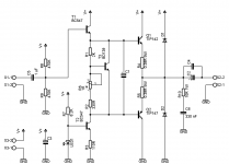
I would like to use bipolar devices, not MOSFETs. This is what I've come up with now:
Output transistors + drivers were replaced by single package darlingtons
CCS sinks ~10 mA for input follower to work into
I still haven't figured out what value of C1 (Vbe multiplier capacitor) to select. Any hints ?
I am still looking for comments regarding the schematic 🙂
Output transistors + drivers were replaced by single package darlingtons
CCS sinks ~10 mA for input follower to work into
I still haven't figured out what value of C1 (Vbe multiplier capacitor) to select. Any hints ?
I am still looking for comments regarding the schematic 🙂
Attachments
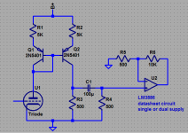
I don't do tube circuits but maybe this would work
current mirror/level shift/divider will have low distortion compared to a SE tube output
power chip amp is about as simple as it gets
can parallel as many as you want from the 500 Ohm gnd referenced divider output R4
current mirror/level shift/divider will have low distortion compared to a SE tube output
power chip amp is about as simple as it gets
can parallel as many as you want from the 500 Ohm gnd referenced divider output R4
Attachments
Last edited:
- Status
- Not open for further replies.