I need to build a relay based power on circuit for my amplifiers that is powered by my PC's 12v output rails. I have a couple of amplifiers that I want power on/ off along with my PC as it turns on and off . Its quite convenient that the PC provides a 12v rail that power on and off along with the PC, it even allows for a power off state in sleep mode, which is exactly what I need. ie amplifiers turn off when PC goes to sleep.
Given that it will power 2 amplifiers (4 toroids 400VA each) will also need a soft start / delay capability. So a straight relay powered by the 12v rails alone will not do. It must be a 2 step (ie soft start) that is triggered by the 12v generated by the PC's power supply. ie no manual on/ off switch is needed.
I have several relays / SSR's available and basic components. Does anyone have a simple schematic I can use (no active devices in the circuit please, I don't want to buy mosfets or worry about mounting them etc.). Just LCR components with perhaps a diode or 2 as needed.
I have power resistors or Thermisters also available.
Anyone have a simple schematic I can build?
I have the following components:
- 12v relays
- 12v SSR's
- 1/4 watt resistors (many)
- 1A diodes
- 30 ohm 50w power resistors (8 of them)
- 1 ohm power resistor 50w (8 of them)
I'd like to avoid using thermisters/ mosfets/ bjts (basically anything that can increase complexity / reduce reliability)
Last edited:
Exactly. TY
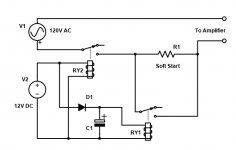
Will it need a resistor between D1 and C1? Otherwise RY1 will try and energize right away. I’d like a 1-2 sec delay.
Also will I need Diodes across the coils to arrest the field collapse when powered off?
What values of R1/C1 do u suggest?
Will it need a resistor between D1 and C1? Otherwise RY1 will try and energize right away. I’d like a 1-2 sec delay.
Also will I need Diodes across the coils to arrest the field collapse when powered off?
What values of R1/C1 do u suggest?
Thanks dotneck. I read this prior to posting. Rod’s articles are a wealth of information. It’s after reading his article that I am favoring relays over SSR’s and Power resistors over NTC limiters. However Rod users active devices in his design. I want to use what I have available.
Yes, I think that's a good idea to insert a small value resistor, just make sure the voltage drop not affect the relay to activate.Will it need a resistor between D1 and C1?
I will said go for it, it's safe better than sorry.will I need Diodes across the coils to arrest the field collapse when powered off?
For the soft start resistor, I think the link provided by dotneck335 already covered it. The capacitor I will use a 2200uF for experiment.What values of R1/C1 do u suggest?
Thanks, I got the Power resistors done, I chose 10 ohms 150watts (three 30 ohm 50watt in parallel). I will experiment with the 2200uF, TY
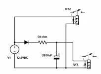

Thanks for your help Chris, I ended up with this circuit. R2 energies after about 1 second, which is what I wanted.
Any observations before I build?
I probably did the neutral symbols incorrectly. None of the AC mains and DC neutral are on the same plane or connected. They are fully isolated to avoid switching noise getting into the amplifier PSU's.
Any observations before I build?
I probably did the neutral symbols incorrectly. None of the AC mains and DC neutral are on the same plane or connected. They are fully isolated to avoid switching noise getting into the amplifier PSU's.
Attachments
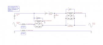
The biggest draw back of this circuit is the delay on relay need time to de-energize after 12V power cut off from the computer power supply. So you have to make sure the relay is de-energized before you turn it on again, otherwise the soft-start resistor will not doing the job.
I think for long run a time delay relay module is a safer way to get the job done.
DC 5V 9V 12V Delay Relay Timing Delay Timer Turn on Delay Turn off Switch Module | eBay
I think for long run a time delay relay module is a safer way to get the job done.
DC 5V 9V 12V Delay Relay Timing Delay Timer Turn on Delay Turn off Switch Module | eBay
I used a large relay which I presume has a lower impedance as it deenergizes in 1-1.5 seconds. Additionally, since the on/ off trigger is via the computer, rapid turn on/ off will not happen. The PC takes 2-3 seconds to sleep or shut off then on.
Project is done. Thanks for everyone’s help.
I had to do a follow up add on for audio as the PC would emit a horrible “Thump” 7-8 seconds after waking up, so I added a 10 sec delay relay on the audio lines too. Works perfectly now.
I had to do a follow up add on for audio as the PC would emit a horrible “Thump” 7-8 seconds after waking up, so I added a 10 sec delay relay on the audio lines too. Works perfectly now.
- Home
- Amplifiers
- Power Supplies
- Powering soft start with PC's 12v Rails