Hey folks, I mentioned this in another thread where I was asking about the driver board for this amp, but so far I have not found an answer. This amp came to me with all the outputs shorted. I replaced them and it powers up and produces audio just fine, but the amp has an annoying turn off thump. No on thump, only off. Perry mentioned checking the class D driver boards "sw" pin which as far as I can tell is the enable for the drive circuit. It behaves exactly as Perry said it should. The turn off thump measures ~-10Vdc on the speaker outputs.
Since then I have replaced all the small driver transistors on the class D driver board. The larger drivers tested ok, so I did not monkey with them. My thoughts were if one side of the drive circuit was leaking at shutdown maybe one bank of fets was getting enhanced and causing the thump. There was no change with this.
I started doing some research and it seems there is a widely popular opinion that this particular design sometimes has a small turn off thump and it is just the way it is... That seems odd to me, but it is a cheap asian amp, so anything is possible.
So, today I am doing a little more testing and I found that on shutdown the positive rail bleeds off voltage much slower than the negative rail. Is that a symptom of the thump or is it possible the asymmetry at shutdown is what is actually causing the thump? I have never dug deep into turn on/off thump on an amp and I am not really sure how to troubleshoot it. If it is just the way it is with these amps, I guess I can accept that, but I had hoped to sell this amp when I was done and I am not willing to send it out with what I feel is still a defect.
Thanks in advance for the input. I appreciate your time!
Thanks,
Jason
I had one of those amp styles that had an off thump I couldn't figure out but worked normally otherwise.It was something in the driver board.Swapping boards at least greatly reduced the thump.
I pulled literally every transistor and most other components and fully tested all of them.Found nothing even questionable.Since there inexpensive,I installed all new transistors....Still a heavy thump.
I never investigated the problem further or tried to mod it.I added a relay and a couple discrete components and that was the fix for that particular amp lol..Took little time and years later,everything's still okay.And practically no thump.
If someone can't help you address it I'm sure I can find my old notes and tell you what I did.
Also,ive seen uneven rail cap discharge rates far from each other (pos&neg of coarse) with no issues with General operation.Even with driver board and outputs etc removed and equal value bleeders.There may be a logical answer in technical form on why negative may zero quicker or vice versa.I would be interesting in knowing if there is a reason at all.
Ok sorry for the rambling.Im assuming the driver board uses to-92 transistors?And you've checked all the norm off of Perrys recommendation and or his tutorial?Does the thump immediately go away or hang for a second or two?
Well I hope we're talking about the same type of board.Regardless a last ditch effort relay can be used on anything really if your dealing with shotty engineering and not necessarily a bad part.
If no one helps, a driver board photo would make sure we're talking about the same board.
I had an amplifier groundzero gzna2500d, this amp is very similar to yours, this was the same problem.
Practically, these types of amplifiers do not use a relay system that retard the ignition on and off in advance to the absence of the remote signal.
For this reason, to solve the problem, Asians have implemented the "sw" pin on the driver board.
This pin inhibits switching when missing the remote signal (turn off the car radio).
It is usually triggered by a BJT transistor that sends this pin to gnd with a signal from the opto couplers on the motherboard (the same ones that drive the operation/protection LEDs ).
You can do a little test.
The moment you turn on the amplifier, if everything is functioning normally, you should see only the red led on, after about 5 seconds, the red LED should turn off and you have to turn on the green LED.
If, when you turn on the amplifier, the red and green LEDs light up together, most likely you have a problem with optocouplers or with the circuit that controls them.
Not sure if you were generally stating or talking to me.I totally understand what he has which is all the common power acoustic,various sound streams etc.
I had a xxx4000D I added a relay too.Which I'm sure took less time than looking and never identifying what the issue was except I knew it was driver board related.
I've heard that depending on size,potential version and which driver board an amp had.Some had a out of the box thump.
I've never seen that but as bad as some of these are made I wouldn't be surprised.
Plus there's a good handful of issues with amps that have the to-220 devices on the driver board.If you find one like that and it actually works and stays working and the outputs don't melt down in 10 sec then I'd say you got lucky.Those amps were pretty bad in general and I've seen many questions regarding how to address the above text.Almost more work than it's worth.
Sorry,besides the various things I said.I wanted a driver board pic to see which type I was looking at.
Is this the all discrete driver board?Like the common q124etc over heat?
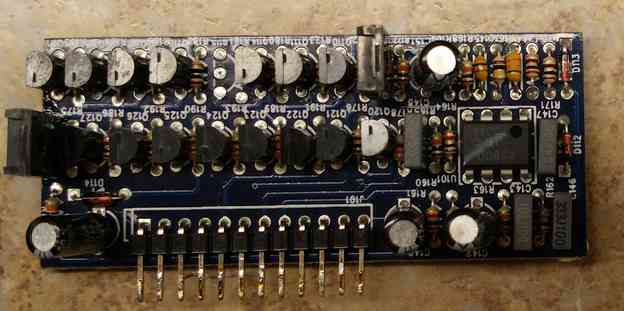
Thanks for the replies folks. The board is functionally the same as the one with the q124/125 problem, but the final set of drivers are in a TO-126 case. I haven't yet seen one with TO-220'S...You would think that would be more robust, but bad engineering is king.
The thump is very brief, a few milliseconds at the most. It's not likely going to damage anything, but I wouldn't run it in my vehicle. I know I can isolate the speakers with a relay and I probably would if I really wanted to run the amp. I know that is the simplest solution but it would be nice to figure out why it's doing this. The amp "muting" circuit, and by that I mean the class d enable is functioning like Perry said it should. When remote voltage is applied it first goes up to positive rail and then almost immediately back to ground. When remote is removed it goes high almost immediately again. One thing I haven't tried to find is if the thump happens before the "sw" pin goes high again.
Here is a picture :
That's sounds identical to what I seen a couple years back.Ended up replacing every part that has an effect on that circuit because technically it was working correctly besides that micro second thump at the end.I do recall when removing a to220 board for the one you have,it was good and bad.Fixed high side output heating problem but had a huge thump when remote was removed.
Wish I could remember more or had one of them style amps here which is usually always except now of coarse.
I know I used one of the opto couplers it has for protection and I think a comparator with various resistors etc.Almost "professionally " so have you.Worked awesome.I know how you feel tho,wanting to know why.
It's not all that uncommon to find faulty designs inside amplifiers.Most can be dealt with so there not talked about.
If you verify that the necessary components are checking okay and if you think it's always been like that.You can investigate making component value changes.Typically not fun.
Do you have another driver board?Another similar amp?
I'll look into the schematic and I do have a driver board and scrap amp.I do know for sure there is slight resistor value changes between some of the driver boards.Most are identical except just a couple resistor value changes.When swapping driver boards in the past,every board worked in every amp but it seemed the turn off thump was different in each configuration.
Kicking myself for never taking good notes and trusting memory.
I'm pretty sure I have an answer but Perry likely has every component memorized and likely found the thumping issues that weren't common and addressed it somehow likely without a relay lol.
Do you have a scope?Ill look through some things and if he hasn't responded I'll try to help.
Q121 and surrounding components to the opto coupler etc you can check and maybe you'll find it.good luck
Correction q113,vpp+ voltage etc..Let me know if you want be to be more specific.Just glancing at the driver board here to give you ideas.Do you know how it's supposed to work in general and have a basic idea about electronics/amplifiers?
What resistance do you read between pin 12 (ground) and pin 13 or pin 15 (12v supply) of the SG3525?
Gosh and don't test the transistors or even the resistors for that matter in circuit.Youll likely be looking for Mohm elec leakage between legs on the transistors.several resistors you may have to lift one leg to check and look closely for burned bottoms of resistors.
I've never seen that board with the larger transistors in place of the "normal" A1023s/1027s
Is vpp~15 above positive rail?At the moment of thump what's the voltage on sw and vpp?
Does it thump with outputs removed?
Sorry if the questions seem elementary or unrelated.
I don't comment often because Perry usually is on top of it so I'll do what I can
Because I'm fully curious if its always been that way and why q113 isn't a a1023 for a specific reason
Out of curiosity and likely the OP as well.Could you let us know why you immediately went to 3525 voltage?
Something to do with remote voltage at some point in the circuit your interested in?
Something to do with remote voltage at some point in the circuit your interested in?
On most of this type of amp, there is a 220 ohm pulldown resistor on the output of the transistor that feeds the 3525. Early versions of this amp didn't have this resistor and that would cause a pop if the remote was cycled quickly (something like starting a car when you go from ignition to start and back to ignition). Adding a pulldown resistor helped. In my notes, it states that a 470 ohm was OK. I don't know if that's the problem here but it's something to check.
Thanks for all the input guys. It looks like I'm not going to make it out to the shop today. I'm watching little ones while my wife took my older daughter shopping. I'll have time tomorrow or at the latest Monday. Thank you for all the info!
Thanks,
Jason
Thanks,
Jason
I'm sure you know this but lead is toxic to small children. Keep them out of the shop area and avoid tracking lead dust into the house on your shoes.
I do Perry, but it does not hurt to have a reminder. The electronics lab is an attic room in my pole barn. The kids are not allowed out there and shoes come off in the garage.
Thanks,
Jason
Thanks,
Jason
SG3525 pin 12 to 13 or 15 is 13K
Guessing this is a version of the amp with no pull down. Should I add it and see what it does?
Thanks,
Jason
Guessing this is a version of the amp with no pull down. Should I add it and see what it does?
Thanks,
Jason
Yes.
I think the fan (if it has one) is across those points. If so, you can simply plug the resistor into the fan connector.
I think the fan (if it has one) is across those points. If so, you can simply plug the resistor into the fan connector.
I used a 360R 1/4w resistor because it was handy and the thump is almost gone. If I wasn't listening for it, I would not have noticed. Should I try the 220R, or leave well enough alone. I am happy with it right now, if 220R will make it completely gone then I would like to try it.
Thanks!
Jason
Thanks!
Jason
I tried 221 Ohm, that is the closest I had. It still has a barely discernible thump, but I am willing to call this fixed. It is so much better than it was.
Perry, I saw that you mentioned this pulldown was included to reduce the thump from short cycling the remote, but while I sometimes cycled it quickly, the thump would occur any time I had let the amp run long enough to enable the Class D board. It did it after running for hours and it would do it after running for 10 seconds. The weird thing is that it would not thump if I cycled remote really quickly. It had to be on for about 5 seconds to get a thump. At first I thought it was a matter of the rail caps not being fully charged, but now I am wondering if it wasn't due to the class D PWM not being enabled yet. Either way, I am calling this a success.
Thank you all so much for your help. I am going back to the SoundStream PIC17000.1 possibly tomorrow. That one is another of these clones but it has a turn off thump about 10x worse than this one and I think the SS amp is bad enough to do damage.
Thanks again!
Jason
- Status
- Not open for further replies.
- Home
- General Interest
- Car Audio
- powerbass ASA3-1500.1D repair help