As general speech, I wondered if instead of a plain resistor of high W sometimes for lowering THD can be suitable a constant current sink on the power tube, like a supertex DN2540 or a IC like IXCP10M45S or other mosfet with specific Gm and linearity . Also, is it always necessary a cascode or can be ok a single configuration too? Thanks.
Hi Indaco, devices like 10M45S can be used in a single configuration. I’ve used them in both plate circuitry and in cathode circuitry as CCS.
Regards, Gerrit
Regards, Gerrit
Ok thanks, in effect I'm looking for simple configuration...here in Italy the device seems not easy to be find, I only can buy it from abroad.
I bought some abroad, quite cheap actually, but I had to wait a long time before they arrived. I’m sure they will be available somewhere in Italy too, but I understand your problem finding them for a good price.
Regards, Gerrit
Regards, Gerrit
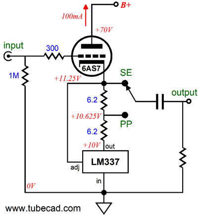
I use LM-317 if the cathode voltage does not over 37vdc. The bias current can be easy set 1.25/ I = R set. Mosfets need to the trimmed individually. Bypass with a quality cap. Using on se 6v6 and pp 6bl7 amps.
If the cathode current is constant, there is no signal on the output transformer.
I suppose you want to keep the DC current constant, but let the AC current changing. Like bypassing the CCS with a capacitor. But then you won't get local negative feedback.
I suppose you want to keep the DC current constant, but let the AC current changing. Like bypassing the CCS with a capacitor. But then you won't get local negative feedback.

If the cathode current is constant, there is no signal on the output transformer.
I suppose you want to keep the DC current constant, but let the AC current changing. Like bypassing the CCS with a capacitor. But then you won't get local negative feedback.
The aim is to be used in OTL configuration, for OT I understand that would be another matter...
Posters,
Please, always start a thread with an accurate description of the problem, topology, and question, and give at least a simplified schematic of the circuit.
What does that accomplish?
It eliminates 5 or 6 answers that have not brought us any closer to the solution.
Please, always start a thread with an accurate description of the problem, topology, and question, and give at least a simplified schematic of the circuit.
What does that accomplish?
It eliminates 5 or 6 answers that have not brought us any closer to the solution.
Ok. Mine was a generic question,. But as an exemple, I can refer to this old Ciuffoli circuit (I hope it is allowed posting the screenshot of the that) where one could replace the set of resistors with a s.s. device, so it also may be smarter and more linearized overall. That was my idea.
Attachments
Last edited:
That plan with 8 * 22k of DC load, the 2,750 ohms of resistance is much higher than almost any headphone you will use, so it makes very little difference 2,750 or infinity.
And if you seriously wanted linearity through more active devices, there are more powerful solutions.
But sure, if you want a MOSFET then use a MOSFET.
And if you seriously wanted linearity through more active devices, there are more powerful solutions.
But sure, if you want a MOSFET then use a MOSFET.
Ok. Mine was a generic question,. But as an exemple, I can refer to this old Ciuffoli circuit (I hope it is allowed posting the screenshot of the that) where one could replace the set of resistors with a s.s. device, so it also may be smarter and more linearized overall. That was my idea.
The 'No-Compromise OTL Tube Headphone Amplifier' is just another example of a design that ignores the Physics of vacuum tubes. The cathode follower is known for low distortion, all of the gain is applied as negative feedback. But what if the gain is rendered low because of a serious mismatch of the tube to the load?
The Spec sheet shews that under certain conditions the Gm of each section is 15 mA/V. Since the load is so much lower than the rp of the tube the gain of the stage can be taken as Gm*Rl, same as a pentode. So paralleling both sections gets 30 mA/V & the headphone load is 32R. Stuffing the numbers into the HP67 & turning the crank I get a gain of 0.96! Not much NFB in that cct. Does anyone ever look at circuit performance using a scope & distortion analyzer? Maybe not, many are afraid of what they will see.
I'm very familiar with the 7119 E182CC, I used quite a few in a research project on a magnetic memory cores. That would be pre 1960.
The 6A3 curve of distortion vs load resistance shews that the power decreases & the D% increases as the load drops below about 2rp. This curve applies to all common triodes no matter what the tube rollers do. But many will continue to insist the result 'sounds OK', whatever that means.
Attachments

> Stuffing the numbers into the HP67 & turning the crank I get a gain of 0.96!
You should try a new crank. For two 15mA/V driving 32r, I get 32/65.3 or 0.49.
You should try a new crank. For two 15mA/V driving 32r, I get 32/65.3 or 0.49.
Your explanation is clear, it's easy moving the crank but a little less with maths 🙂 Why not to use, for example, 6H30 tube (Audio Research used them too...): higher plate current and higher μ. A part this, I feel that on driving low Z headphones I would go for OT instead.
> Stuffing the numbers into the HP67 & turning the crank I get a gain of 0.96!
You should try a new crank. For two 15mA/V driving 32r, I get 32/65.3 or 0.49.
No need for a new crank yet, the calculation is for any tube cct where the Rl (load) impedance is significantly less than the tube rp.
Think you went straight to the gain of the cct while connected as a CF.
So to calc that when all the gain is applied as NFB the gain become
A/ (A + 1).
Stuffing the numbers into that the HP 67 sez 0.49, same as you got.🙂
Your explanation is clear, it's easy moving the crank but a little less with maths 🙂 Why not to use, for example, 6H30 tube (Audio Research used them too...): higher plate current and higher μ. A part this, I feel that on driving low Z headphones I would go for OT instead.
Good for Audio Research, perhaps they didn't read the books on vacuum tubes either! Doesn't matter who builds the amplifier at all, for a proper match a triode needs to see a load at least 2X its rp. Very few tubes can do that for a 32 ohm load.. An OPT is a far better idea.🙂
The proper load is the same whether it is in the plate lead or the cathode lead. Or split as it is in the split load phase inverter.🙂
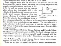
Fred E Terman & the Inverted Triode
In a 1928 IEEE paper Fred E Terman described using a triode where the plate & grid connexios are interchanged. That way the plate is the controlling electrode while the output is taken from the grid. It was possible to create a rather low impedance output from the grid.
Much later Steve Bench built several audio amplifier based on this principle using multiple tubes such as the 5687 & 6080. I looked at his web site this AM, it seems much of the information has been taken down.
Hopefully someone has created a mirror so that the information is not lost.
Steve's Tube Pages
Attachments
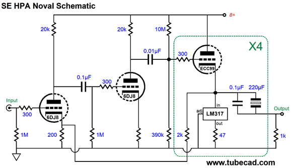
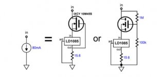
You can do stuff like this:Also, is it always necessary a cascode or can be ok a single configuration too?
More OLT Design
Circlotron & Book Review
Steve Bench Link
Steve's Tube Pages
A Cornucopia of information, real circuits complete with test results.
Look thru the list, you will find information covering amplifiers built based on the inverted triode connexion.🙂
Steve's Tube Pages
A Cornucopia of information, real circuits complete with test results.
Look thru the list, you will find information covering amplifiers built based on the inverted triode connexion.🙂
The screenshot of LM317/337 would be ok but within a low-medium voltage...my question was for various voltages or currents.
Just to stay on the initial topic where I mentioned the use of IC/mosfet I found this. Maybe one could replace the current regulator with another, this one is by default.
Just to stay on the initial topic where I mentioned the use of IC/mosfet I found this. Maybe one could replace the current regulator with another, this one is by default.
Attachments
Yes, absolutely use a CCS there. The AC impedance of the CCS will be many orders of magnitude higher than the AC impedance of all those resistors in parallel, allowing for additional AC signal current to be delivered to the headphones rather than wasted in the cathode resistors.
(A 5842 absolutely needs grid stoppers and plate stoppers too)
(A 5842 absolutely needs grid stoppers and plate stoppers too)
- Home
- Amplifiers
- Tubes / Valves
- Power tube cathode bias (CCS)